Table of Contents
Advertisement
Quick Links
Advertisement
Table of Contents

Subscribe to Our Youtube Channel
Related Manuals for Sensia CD20

Summary of Contents for Sensia CD20
- Page 1 Clif Mock CD20 (230VAC) Sampler Drive User Manual Manual No. 20165011A...
- Page 2 © 2004 NuFlo Technologies, Inc. All information contained in this publication is confidential and proprietary property of NuFlo Technologies, Inc. Any reproduction or use of these instructions, drawings, or photographs without the express written permission of an officer of NuFlo Technologies, Inc.
-
Page 3: Table Of Contents
Start-up Procedure......................3 Pre-Test Procedure ..................... 3 Repeat Mode Check-Out ..................... 3 External Input Pulse Mode Check-Out ................ 3 Sample Probe and CD20 Check-Out................3 Motor Control Operation....................4 Control Card Functions....................4 Power Board Functions ....................4 Troubleshooting ......................5 Sampler Drive Schematic ..................... - Page 4 April 2004...
-
Page 5: Description
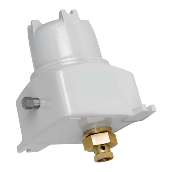
The CD20 mounts directly to the C-Series sample probe via the DC-2 coupling. The DC-2 coupling should be hand-tightened to ensure that the internal retaining ring is not pushed out of its groove. If the DC-2 coupling is over-tightened at the CD20 hub, the motor shaft will not engage the DC-1 coupling on the probe. - Page 6 Figure 1—Field wiring of CD20 (230VAC) assembly Figure 2—CD20 (230VAC) control card (full view) April 2004...
-
Page 7: Start-Up Procedure
(“Hold”) LED is on while the motor is stopped. 4. Verify that the CD20 output shaft rotates in a clockwise direction as you look at the shaft. The sample probe will be rotated counterclockwise (CCW) when the CD20 drive is connected to it. If the direction of motor rotation is wrong, swap the motor armature leads at 2TB-1 and 2TB-2. -
Page 8: Motor Control Operation
The CD20 motor control assembly consists of a control card and power board mounted to a ring, which in turn, is mounted to the back of the CD20 gear motor. All field connections are to terminal block 1TB on the control card. The motor and proximity switch connections are made at the factory to terminal block 2TB on the power board. -
Page 9: Troubleshooting
To isolate the problem, power down and remove the motor is stopped. motor armature is driving the the CD20 from the probe and verify CD20 output probe backwards (CW) against shaft turns CW as you look at it in repeat mode. - Page 10 Probable Cause Recommended Action Motor does not run Input pulses are not present at Use a separate switch input to verify the CD20 is (cont’d). 1TB-5 and 1TB-6. operating correctly in pulse mode. Use a portable oscilloscope to verify proper pulse input.
-
Page 11: Sampler Drive Schematic
April 2004... -
Page 12: Bill Of Materials
50142307693 BINDER HD SCREW, #8-32NC x 1/2" 50142307694 WASHER HUB SCREW, #8 50142304642 BREATHER, 1/2" PLUG 50142400194 JUMPER, RDI #J4-02 50142200109 CAUTION TAG, CD20, CD20A, CD30 DRIVES 50142304858 HUMISORB PACKET, #107HX 4 x 4 50142307670 STICKER, CD20 230VAC April 2004... - Page 13 WARRANTY - LIMITATION OF LIABILITY: Seller warrants only title to the products, software, supplies and materials and that, except as to software, the same are free from defects in workmanship and materials for a period of one (1) year from the date of delivery.
Need help?
Do you have a question about the CD20 and is the answer not in the manual?
Questions and answers