Sign In
Upload
Download
Table of Contents
Contents
Add to my manuals
Delete from my manuals
Share
URL of this page:
HTML Link:
Bookmark this page
Add
Manual will be automatically added to "My Manuals"
Print this page
×
Bookmark added
×
Added to my manuals
Manuals
Brands
Flott Manuals
Drill
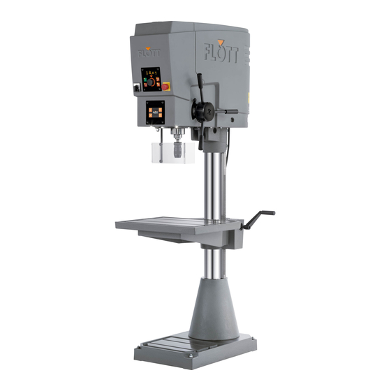
SB 30 NC Plus
Operating manual
Flott SB 30 NC Plus Operating Manual
Hide thumbs
1
2
Table Of Contents
3
4
5
6
7
8
9
10
11
12
13
14
15
16
17
18
19
20
21
22
23
24
25
26
27
28
29
30
31
32
33
34
35
36
37
38
39
40
41
42
43
44
45
46
47
48
49
50
51
52
53
54
55
56
57
58
59
60
61
62
63
64
65
66
67
68
69
70
71
72
73
74
75
76
77
78
79
80
81
82
83
84
85
86
87
88
89
90
91
92
93
94
95
96
97
98
99
100
101
102
103
104
105
106
107
108
109
110
111
112
113
114
115
116
117
118
119
120
121
122
123
124
page
of
124
Go
/
124
Contents
Table of Contents
Troubleshooting
Bookmarks
Table of Contents
Table of Contents
Contents
Introduction
Column Drill Press
Technical Data
Column Drill Press Type Plate
Proper Use
Improper Use
Legal Provisions
Liability
Warranty
Copyright
Operating Manual
Terminology
Visual Representations and Distinctions in Text
Structure and Design of the Safety Instructions
Safety Information
General Safety Instructions
Operating Manual
Obligations of the Operator
Safety of the Machine
The Personnel Carrying out the Work
The Workplace
Safety Information for Using the Machine
Transport to the Installation Site
Commissioning, Operation, Decommissioning
Maintenance and Repair
Disposal
Machine Safety Equipment
Technical Description
Function Description
Overview of the Machine
Installing the Machine
Before Using the Machine
Assemble Accessories and Optional Components
Mounting the Drill Chuck
Mounting the Tool
Setting and Operating the Drilling Protection
Mounting the Machine Vice
Adjusting the Height of the Machine Table
Connecting the Electrical Aspects of the Machine
Checks Prior to Commissioning
Operating the Machine
Machine Controls
Accessing the Operator Menu on the Control System
Manual Mode
Drilling a through Hole
Carrying out Drilling with a Fixed Stop
Carrying out Drilling with Depth Setting
Thread Cutting with Depth Setting
Changing the Drilling Parameters
Functions of the Ancillary Panel in Manual Mode
Automatic Mode
Switching between Manual and Automatic Mode
Structure of Automatic Mode
Default Settings in Automatic Mode
Inching Mode (Manual-Automatic)
Automatic Drilling
Automatic Thread Cutting
Wizard - Assistant for Selecting Machine Parameters
Stage Programming
Stage Programming Overview
Selection of the Operating Mode (Stage Programme)
Special Operating Modes
Create Individual Stage Programme
Save Stage Programme
Delete a Stage Programme
Accessing and Loading a Stage Programme
Activating or Deactivating the Prompt
Switching off the Machine
Activate Machine's EMERGENCY Stop
Signal Exchange Option
Troubleshooting
Error Message on the Display
Other Errors and Solutions
Release of the Machine after an Error
Machine Maintenance
Testing and Maintenance Intervals
Disassembly of the Drill Chuck
Dis)Assembling the Protective Cover
Opening the Front Protective Cover
Dismantling the Rear Protective Cover
Assembling the Rear Protective Cover
Tensioning And/Or Replacing the Belt
Machine Type Without Transmission (R1 and R2)
Machine Type with Transmission (R3)
Lubrication Schedule
Repairs
Spare Parts List
Technical Drawings and Plans
EC Declaration of Conformity
Notes
Advertisement
Quick Links
Download this manual
OPERATING
MANUAL
SB 30 NC Plus
SB 40 NC Plus
SB 40 NC FB Plus
Table of
Contents
Previous
Page
Next
Page
1
2
3
4
5
Advertisement
Table of Contents
Need help?
Do you have a question about the SB 30 NC Plus and is the answer not in the manual?
Ask a question
Questions and answers
Related Manuals for Flott SB 30 NC Plus
Drill Flott Turbo Drill Operating Instructions Manual
(29 pages)
Drill Flott TBZ 13 Plus Operating Manual
(80 pages)
Drill Flott E3 Operating Instructions Manual
(21 pages)
Drill FLOTT S 25 U Operating Instructions Manual
(11 pages)
Drill Flott SB 18 Plus Operating Manual
(99 pages)
Drill Flott SB 40 NC Plus Operating Manual
(124 pages)
Drill Flott SB 15 Plus Operating Manual
(80 pages)
Drill Flott SB 15 Operating Instructions Manual
(24 pages)
Drill Flott TB 10 eco Plus Operating Instructions Manual
(15 pages)
Drill Flott P 30 STG PV Operating Instructions Manual
(47 pages)
Drill Flott M3 ST MV Manual
(20 pages)
This manual is also suitable for:
Sb 40 nc plus
Sb 40 nc fb plus
230.510
230.511
230.512
230.513
...
Show all
230.525
230.526
230.527
230.540
230.541
230.542
Table of Contents
Print
Rename the bookmark
Delete bookmark?
Delete from my manuals?
Login
Sign In
OR
Sign in with Facebook
Sign in with Google
Upload manual
Upload from disk
Upload from URL


Need help?
Do you have a question about the SB 30 NC Plus and is the answer not in the manual?
Questions and answers