
Related Manuals for Flott SB 18 Plus


Summary of Contents for Flott SB 18 Plus
- Page 1 Operating Manual SB 18 Plus TBZ 18 Plus SB 20 Plus TBZ 20 Plus SB 23 Plus TBZ 23 Plus SB 25 Plus TBZ 25 Plus TB 18 Plus TB 20 Plus SB 20 FB Plus TB 23 Plus TB 25 Plus...
- Page 2 Contents Important Notice! This operating manual has been prepared in the German language, which is the language of the original. All versions available in other languages are only the translations of the German original operating manual. 0 4 / 0 3 / 2 0 2 0 2 1 8 3 3 3...
-
Page 3: Table Of Contents
Contents Contents Contents Introduction Pillar Drilling Machine ..................... 7 1.1.1 Technical Data ..................7 1.1.1 Technical Data ..................8 1.1.2 Rating Plate of the Pillar Drilling Machine ..........9 1.1.3 Intended Use ..................10 1.1.4 Improper Use ..................10 Legal Provisions ....................11 1.2.1 Liability .................... - Page 4 Contents Technical Description Functional Description ..................26 Machine Overview ....................27 Installation of the Machine Before Using the Machine Mounting Accessories and Options ............... 30 5.1.1 Mounting Drill Chuck ................30 5.1.2 Installing the Cutter ................31 5.1.3 Set Drill Guard and Press ..............32 5.1.4 Installing Machine Vice .................
- Page 5 Contents Troubleshooting Error Messages on the Display ................58 Other Malfunctions and Remedies................ 59 Release of the Machine After a Fault ..............60 Maintenance of the Machine Inspection and Maintenance Intervals ..............61 Dismantling Drill Chuck ..................63 Installing/Removing the Protective Hood .............. 65 9.3.1 Removing the Protective Hood..............
-
Page 6: Introduction
Always close to its customers – "High Quality – made in Ger- many". With its partners in Europe, FLOTT is not only rich in tradition but is al- so one of the leading manufacturers of state-of-the-art, high-quality drilling, sawing and grinding machines in Europe. -
Page 7: Pillar Drilling Machine
Introduction Pillar Drilling Machine 1.1.1 Technical Data Type SB 18 Plus TB 18 Plus TBZ 18 Plus Order No. 218.308 218.303 218.309 Permanent/normal drilling perfor- [mm] 18/20 mance Thread cutting performance [mm] max. M12 Spindle holder Type Drilling depth [mm]... -
Page 8: Technical Data
Introduction 1.1.1 Technical Data Type SB 23 Plus SB 23 Plus TBZ 23 Plus Order no. R1 223.020 223.021 223.022 Order no. R2 223.025 223.026 223.027 Permanent/normal drilling [mm] 23/25 (R1) performance 20/23 (R2) Thread cutting performance [mm] max. M16 (R1) max. -
Page 9: Rating Plate Of The Pillar Drilling Machine
Bohrmaschine 18 Plus, 20 Plus, 23 Plus, 25 Plus xxx.xxx Manufacturer: Arnz FLOTT GmbH Werkzeugmaschinen Vieringhausen 131 42857 Remscheid, Germany Tel: +49 21 91 979-0 Fax: +49 21 91 979-222 e-mail: info@flott.de... -
Page 10: Intended Use
Damage to the machine Damage to other property. Any improper use without exception is an action taken at the sole risk of the user. Any resulting liability claims against Arnz FLOTT GmbH Werkzeug- maschinen are excluded unless otherwise required by mandatory statutory provisions. -
Page 11: Legal Provisions
Arnz FLOTT GmbH Werkzeugmaschinen or as a buyer after a reselling original purchaser, the lia- bility of Arnz FLOTT GmbH Werkzeugmaschinen is limited to the liability under the Product Liability Act and under the general statutory provisions provided this operating manual has been adhered to. -
Page 12: Warranty
Introduction 1.2.2 Warranty Warranty claims shall be submitted to Arnz FLOTT GmbH Werkzeugmaschi- nen immediately after the error or defect has been identified, stating the ma- chine number, the machine type and the serial number. Wear parts are not subject to warranty. The warranty is null and void in case... -
Page 13: Operating Manual
Introduction Operating Manual This operating manual contains information and instructions which shall en- sure that the operating personnel can work safely, properly and economically on and with the machine. Only if the contents of the operating manual are un- derstood and observed, can Help to avoid hazards Reduce repair costs and downtime and Increase the reliability and service life of the machine. - Page 14 The technical staff are familiar with the accident prevention regulations, the relevant regulations and the operating conditions. Personnel of Arnz FLOTT GmbH Werkzeugmaschinen Personnel of Arnz FLOTT GmbH Werkzeugmaschinen is who is technical staff and employee of Arnz FLOTT GmbH Werkzeugmaschinen. Residual risks Residual risks are not obvious risks that are given during the operation of the machine.
-
Page 15: Illustrations And Signs In This Text
Introduction 1.3.2 Illustrations and Signs in this Text To emphasize important information, this manual uses the following picto- grams, symbols and typographical signs. Pictograms General danger Indicates safety instructions which must be observed and which cannot be identified with a specific pictogram (e.g. one of the following pictograms). High electrical voltage Indicates the risk of electric shock. -
Page 16: Structure And Design Of Safety Instructions
Introduction Symbols The operating manual uses three different symbols: This symbol indicates a single handling instruction. If there are more than one instruction, they are numbered consecutively. This symbol indicates lists that consist of equal content. This symbol identifies subitem lists that are subordinate to the lists and also consist of equal content. - Page 17 Introduction Examples of safety instructions Warning Danger by improper use of the machine. The machine may only be operated by authorized and trained personnel. The machine may only be operated when it is in flawless condition. All safety devices must be present and fully functional. Note Check all screw connections before commissioning the machine Tight fit...
-
Page 18: Safety Instructions
If you do not understand this operating manual or individual paragraphs, you should not start your activity. Ask the technical staff of the operating company or of Arnz FLOTT GmbH Werkzeugmaschinen before you get into a potentially dangerous situation. 0 4 / 0 3 / 2 0 2 0... -
Page 19: The Duties Of The Operating Company
Check all safety devices for proper operation before operating the machine. Note Modifications, extensions and conversions of the machine that impair safety are strictly prohibited. They require the written approval of Arnz FLOTT GmbH Werkzeugmaschinen. 2 1 8 3 3 3... -
Page 20: The Working Staff
Safety Instructions Only use original spare parts if you need to replace components of the ma- chine. Operation and safety of the machine are preserved only with original spare parts. 2.1.4 The Working Staff Only authorized and trained personnel may work on and with the machine. Unauthorized persons are prohibited from using the machine. -
Page 21: Safety Instructions For The Use Of The Machine
Safety Instructions Safety Instructions for the Use of the Machine Use safety goggles Always wear the necessary goggles when working on and with the machine! Use safety shoes Always wear the necessary safety shoes when working and with the machine! Use protective clothing Always wear the necessary tight-fitting protective clothing when working on and with the machine! -
Page 22: Commissioning, Operation, Decommissioning
Safety Instructions 2.2.2 Commissioning, Operation, Decommissioning Danger Danger by electric voltage. The machine (class A) is designed according to EN55011 for an industrial en- vironment. In other environments, appropriate measures on part of the operat- ing company may be necessary. Warning Danger due to improper work on and with the machine. -
Page 23: Maintenance And Repair
Safety Instructions Attention Danger due to inadequate lighting. The operator of the machine must ensure that there is adequate lighting to operate the machine. Attention Danger due to sharp-edged swarf. Do not remove swarf with your bare hands. The blowing out with compressed air is also unsuitable, since the swarf can easily get into the eye. -
Page 24: Disposal
Safety Instructions Danger Danger due to improper maintenance of the machine. Only authorized and trained personnel may carry out the cleaning of the machine and the maintenance. For the machine to remain safe and have a long service life, you must comply with the maintenance works and intervals that are specified in this operating manual. -
Page 25: Safety Devices Of The Machine
Safety Instructions Safety Devices of the Machine For the safety devices on the machine, see the figure in section 3.2 Machine overview on the page 27. Protective hood The protective hood serves as protection against intervention in the rotating drive unit and the electrical components. The protective hood may only be re- moved from the machine by qualified personnel for maintenance and repair. -
Page 26: Technical Description
Technical Description Functional Description FLOTT pursued high standards in developing the PLUS series. The goal was not another type of drilling machine – but drilling technology that is years ahead of the time. Innovative in ergonomics and design, which keeps FLOTT firmly anchored in the market "as a brand"... -
Page 27: Machine Overview
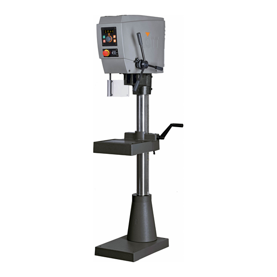
10 Lighting / coolant switch Clamping lever Emergency stop button Hand crank 12 Operator panel Toothed rack 13 Protective hood Three-arm-lever 14 Adapter Machine type: SB 18 Plus 2 1 8 3 3 3 0 4 / 0 3 / 2 0 2 0... -
Page 28: Installation Of The Machine
Installation of the Machine Installation of the Machine The machine usually comes packaged on a small pallet. Bear in mind the weight of the machine and, if necessary or appropriate, use transport equip- ment or a second person. Warning Danger of falling down of the transported object. The machine may only be transported by authorized personnel. - Page 29 Installation of the Machine 6. Mark the holes for fixing the machine base. 7. Move the machine slightly and drill out the holes (depending on the design with 2 or 4 through holes or dowel holes for M12). 8. Place suitable vibration dampers (rubber mat or rubber damper) under the machine base in order to absorb vibrations during operation.
-
Page 30: Before Using The Machine
Before Using the Machine Before Using the Machine Mounting Accessories and Options Depending on the order, the machine comes without machine vice and drill chuck. These optional components must be properly installed by the operator after the machine has been set up. 5.1.1 Mounting Drill Chuck 1. -
Page 31: Installing The Cutter
Before Using the Machine 5.1.2 Installing the Cutter Depending on how the workpiece is to be machined, the appropriate cutter (drill, countersink, reamer or tap) must be inserted into the chuck. Note Please note The technical data of this operating manual, in particular with regard to the performance limits and The technical data of the cutter manufacturer. -
Page 32: Set Drill Guard And Press
Before Using the Machine 5.1.3 Set Drill Guard and Press The drill guard is an important safety device of the machine and can be both adjusted in height and swung sideways. For the machining process, the height of the drill guard must be set correctly and swung as far as possible in the direction of the cutter. - Page 33 Before Using the Machine Operating drill guard The drill guard is equipped with a protective switch in the machine housing. Only when the drill guard is swivelled to its protection position, the protective switch is activated and only then is released by the control system for opera- tion.
-
Page 34: Installing Machine Vice
Before Using the Machine 5.1.4 Installing Machine Vice The drilling table is used to safely secure the workpiece to be machined. Clamping jaws or a vice can be secured with the T-blocks in the T-recesses in the drilling table. These aids are used to secure the workpiece against rota- tion. -
Page 35: Adjusting The Height Of The Machine
Before Using the Machine Adjusting the Height of the Machine Depending on the design of the machine, the drilling table or the machine head can be adjusted in height. This is always necessary if the distance from the drilling spindle to the workpiece has to be changed. 1. -
Page 36: Connecting The Machine Electrically
Before Using the Machine Connecting the Machine Electrically Warning Danger due to faulty electrical connection. Observe the electrical connection values in the operating manual and the rat- ing plate when connecting the machine. Excessive connection voltage may cause operator injury and damage to the machine. -
Page 37: Checks Before Commissioning
Before Using the Machine Checks Before Commissioning Before putting the machine into operation, you need to check some points. These checks are needed for the safety and work preparation of all persons working on the machine. Take the utmost care in these checks so that you do not unnecessarily endan- ger yourself, other persons or the machine. -
Page 38: Operating The Machine
Operating the Machine Operating the Machine Read and observe the safety instructions in this operating manual before per- forming any work on and with the machine (see section 2.2 Safety instructions for the use of the machine, page 21). Control Elements of the Machine The machine has 4 important control elements, which are used by the opera- tor to operate the machine: The control panel with display... - Page 39 Operating the Machine Item Image Type Function Emergency Turns off the drive and the drill light. The display remains stop button switched on until the supply voltage of the frequency converter dies off. The button is used in every situation as an emergency stop button.
- Page 40 Operating the Machine Item Image Type Function Three-arm- The operator moves the spindle up and down using the drill lever lever during the machining operation. Fixed limiter Is used during the drilling operation to mechanically limit a drilling depth. The limiter is active when it is pushed completely onto the three-arm-lever axle.
- Page 41 Operating the Machine Digital display The display is integrated into the control panel and is used to display error messages (superimposed on all other displays) (1) Spindle speed (2) Display of active drilling style (drilling or tapping) (3) Drilling depth as actual value (4) Drilling depth as setpoint (5) Piece counter of already executed holes 2 1 8 3 3 3...
-
Page 42: Drilling Through Hole
Operating the Machine Drilling Through Hole Use safety goggles Always wear the necessary goggles when working on and with the machine! Warning Danger due to fast rotation of the drill spindle. Fast rotation of the drill spindle can result in hair or clothing being pulled in. This can lead to serious injuries. - Page 43 Operating the Machine 4. Before starting the machine, swivel the drill guard into its protection position in front of the cutter. This will activate the protective switch, which releases the operation of the machine. 5. If necessary: Press the push-button to select the drill type Drilling. The top left lamp lights when the drilling mode is selected.
-
Page 44: Drilling Hole With Limiter
Operating the Machine Drilling Hole with Limiter You can use the limited if a small series of holes with the same drilling depth is to be drilled. Limiter equipped with freewheel ensures the required drilling depth through mechanical limitation during the drilling operation. Use safety goggles Always wear the necessary goggles when working on and with the machine! Warning... - Page 45 Operating the Machine 4. Before starting the machine, swivel the drill guard into its protection position in front of the cutter. This will activate the protective switch, which releases the operation of the machine. 5. If necessary: Press the push-button to select the drill type Drilling. The lower right lamp lights when the Drilling mode is selected.
-
Page 46: Bore With Depth Adjustment
Operating the Machine Bore with Depth Adjustment The depth adjustment of the control system is only connected to an acoustic signal, there is no mechanical or technical limitation of the drill hole depth. Since the drilling process is carried out manually with the three-arm-lever, it is also possible to drill deeper after the signal. - Page 47 Operating the Machine 4. Before starting the machine, swivel the drill guard into its protection position in front of the cutter. This will activate the protective switch, which releases the operation of the machine. 5. If necessary: Press the push-button to select the drill type Drilling. The top left lamp lights when the drilling mode is selected.
- Page 48 Operating the Machine 11. Use the three-arm-lever to slowly move the drill bit towards the workpiece by pressing down on the three-arm-lever. Drill the through hole or blind hole in the workpiece. As soon as the pre-set drilling depth is reached, a signal ("beep") sounds. In addition, the drilling depth is shown in the display.
-
Page 49: Tapping With Depth Adjustment
Operating the Machine Tapping with Depth Adjustment Tapping is carried out with a tap suitable for the pre-drilled hole. As soon as the pre-set threading depth is reached, the direction of rotation of the spindle automatically reverses so that the tap is move out of the cut thread. Use safety goggles Always wear the necessary goggles when working on and with the machine! Warning... - Page 50 Operating the Machine 4. Before starting the machine, swivel the drill guard into its protection position in front of the cutter. This will activate the protective switch, which releases the operation of the machine. 5. If necessary: Press the push-button to select the drilling type Tapping. The lower right lamp lights when the Tapping mode is selected.
- Page 51 Operating the Machine Note Slightly correct the position of the spindle with the drill lever when cutting a thread. This will relieve the tensile force on the thread. This is especially im- portant for soft materials. 11. Use the three-arm-lever to slowly move the tap towards the workpiece by pressing down on the three-arm-lever.
-
Page 52: Changing Drilling Parameters
Operating the Machine Changing Drilling Parameters Changing speed The spindle speed can be changed at any time during a process. Adjust the speed accordingly by pressing the rotary switch/push-button Set the speed (rpm) by turning slowly and Apply the speed in the control system by pressing. The set speed is shown in the display. - Page 53 Operating the Machine Setting spindle stop In the control system you can basically set whether the spindle Remains permanently on after the machine start (until the machine stops) Is switched off automatically after the drilling operation and reaching the upper spindle position. This can for example be useful for safety reasons. In the basic setting, the spindle stop is switched off and can be set accordingly in the operator menus.
-
Page 54: Calling Up The Operator Menu Of The Control System
Language Sets the language of the dis- English play. Service pass- Enables the input of the service password exclusively for word FLOTT service technicians. 0 4 / 0 3 / 2 0 2 0 2 1 8 3 3 3... -
Page 55: Shutting Down The Machine
Shutting Down the Machine Shutting Down the Machine Switching the Machine Off Warning Danger due to faulty electrical connection. Observe the electrical connection values in the operating manual and the rat- ing plate when connecting the machine. Excessive connection voltage may cause operator injury and damage to the machine. -
Page 56: Press Emergency Stop Of The Machine
Shutting Down the Machine Press Emergency Stop of the Machine The control panel emergency stop button is used by the operator as a safety switch while working on and with the machine. You can use the emergency stop button to immediately stop all drives and movements of the machine in the event of imminent danger, regardless of the currently selected operating mode or function. -
Page 57: Measures Before Maintenance And Repair
Shutting Down the Machine Measures Before Maintenance and Repair Danger Danger by electric voltage. Maintenance work on electrical components may only be carried out by au- thorized personnel (electricians). Make sure that the electrical equipment of the machine is de-energized for the period of maintenance. Wait at least 15 minutes before removing the protective hood of the machine. -
Page 58: Troubleshooting
Unlock emergency stop but- ton. If this does not help: Acknowledge with or rotary switch/push-button or Restart the machine or Contact FLOTT Service. Display off Machine is in standby mode. Acknowledge with the rotary switch/push-button. If this does not help: Restart the machine or Contact FLOTT Service. -
Page 59: Other Malfunctions And Remedies
Troubleshooting Other Malfunctions and Remedies The following table shows further faults and their elimination, which are not shown on the display. Warning Danger due to improper troubleshooting. Improper troubleshooting can result in danger to the operating staff and to the machine. -
Page 60: Release Of The Machine After A Fault
Troubleshooting Release of the Machine After a Fault Warning Danger due to improper troubleshooting. Improper troubleshooting can result in danger to the operating staff and to the machine. Specialized work on the mechanics and electrics may only be carried out by technical staff. -
Page 61: Maintenance Of The Machine
Maintenance of the Machine Maintenance of the Machine Inspection and Maintenance Intervals The following list for regular maintenance gives an overview of the minimum scope of works required to ensure trouble-free operation. It depends on the respective operating conditions and the utilization of the machine whether and to what extent further care and maintenance is required. - Page 62 Maintenance of the Machine Maintenance interval Assembly Maintenance activities group Danger Before starting any maintenance or cleaning work, you must shut down the machine ( (see section 7 Shutting down the machine). Free the machine from swarf. Use a hand brush. Machine in general Free machine and area around the machine from cooling lubricants.
-
Page 63: Dismantling Drill Chuck
Maintenance of the Machine Dismantling Drill Chuck Danger Danger due to unintentional start-up of the machine. You must shut down the machine prior to starting any maintenance or cleaning work. Attention Damage to the spindle or drill chuck. Make sure that when dismantling the chuck, it does not fall onto the drilling ta- ble or vise. - Page 64 Maintenance of the Machine 7. Gently tap the end of the pin punch with a hammer, this will release the chuck from the spindle. 8. Remove the chuck. 9. Check the drill chuck and spindle for dirt, wear or damage. 0 4 / 0 3 / 2 0 2 0 2 1 8 3 3 3...
-
Page 65: Installing/Removing The Protective Hood
Maintenance of the Machine Installing/Removing the Protective Hood In order to carry out the various maintenance and repair work on the electrical system and the drive unit, the protective hood of the machine must be disman- tled. Danger Danger by electric voltage. Maintenance work on electrical components may only be carried out by au- thorized personnel (electricians). - Page 66 Maintenance of the Machine 5. In the area ofthe spindle, loosen the size 4 hexagon socket screw to remove the three-arm-lever. 6. Carefully pull the complete three-arm-lever with pinion shaft out of the guide of the quill and deposit it. 7.
- Page 67 Maintenance of the Machine 17. Loosen the drilling depth limiter with a WAF13 hexagon wrench and remove it. 18. Remove the 2 side Phillips screws from the protective hood. 19. Tilt the protective hood slightly forward and pull it down from the machine head.
-
Page 68: Installing The Protective Hood
Maintenance of the Machine 9.3.2 Installing the Protective Hood 1. Put the protective hood slightly tilted forward on the ma- chine head. 2. Feed the connection cables for the control panels through the individual openings of the protective hood. 3. Lower the protective hood onto the machine head and make sure that it fits correctly. - Page 69 Maintenance of the Machine 6. Plug in the power plug and the multipolar connector into the respective connector sockets on the back of the upper control panel. 7. Place the control panel in the upper insert of the protec- tive hood. 8.
- Page 70 Maintenance of the Machine 12. Push the complete three-arm-lever with pinion shaft slowly into the guide of the quill as far as it will go. You have to Make sure not to force the pinion shaft into the guide as this can damage the very accurately machined quill surface If necessary, turn the pinion shaft slightly during inser- tion so that it slides into the teeth.
- Page 71 Maintenance of the Machine 19. Insert the large black protective plug on the left side of the protective hoods. 20. The protective hood is now installed and the machine can be used again. 2 1 8 3 3 3 0 4 / 0 3 / 2 0 2 0...
-
Page 72: Tensioning Or Replacing Ribbed V-Belt
Maintenance of the Machine Tensioning or Replacing Ribbed V-belt In order to carry out the various maintenance and repair work on the electrical system and the drive unit, the protective hood of the machine must be disman- tled. Danger Danger by electric voltage. Maintenance work on electrical components may only be carried out by au- thorized personnel (electricians). - Page 73 Maintenance of the Machine For all SB/TB/TBZ 18/20/23 Plus types 4. On the top of the motor bracket, loosen the two hexagon socket screws to loosen the motor and rear pulley. This will relieve the tension of the ribbed V-belt. Note Please note that only original spare parts from the manufacturer May be used.
- Page 74 Maintenance of the Machine Only for SB/TB/TBZ 23/25 Plus types In these machine types, 2 ribbed V-belts are installed on 3 axles so that 2 ribbed V-belts must be tensioned if necessary. If the front ribbed V-belt is ten- sioned, the rear ribbed V-belt must also be tightened. 4.
-
Page 75: Replacing Control Panels
Maintenance of the Machine Replacing Control Panels In the event that the control panel or button of the control panel are defective, the control panel must be replaced as a whole. Danger Danger by electric voltage. Maintenance work on electrical components may only be carried out by au- thorized personnel (electricians). - Page 76 Maintenance of the Machine 5. Remove the control panel and replace it with a new one. 6. Plug in the power plug and the multipolar connector into the respective connector sockets on the back of the control panel. 7. Place the control panel in the insert of the protective hood.
-
Page 77: Lubrication Schedule
Maintenance of the Machine Lubrication Schedule 2 1 8 3 3 3 0 4 / 0 3 / 2 0 2 0... -
Page 78: Repair
Maintenance of the Machine Repair Most of repair work requires special knowledge of materials, components, test stands and equipment. Therefore, this work must only be carried out in consul- tation with the manufacturer. Danger Danger by electric voltage. Repair work on electrical components may only be carried out by authorized personnel (electricians). -
Page 79: Spare Parts List And Drawings
Spare Parts List and Drawings This does not apply to parts no longer manufactured due Order number to technical innovations! Fig. Item Designation SB 18 Plus TB 18 Plus TBZ 18 Plus Protective hood 218321 218321 218321 Control panel *... - Page 80 Spare Parts List and Drawings This does not apply to parts no longer manufactured Order number due to technical innovations! Fig. Item Designation SB 18 Plus TB 18 Plus TBZ 18 Plus Bolt * 169243 169243 169243 Worm wheel *...
- Page 81 Spare Parts List and Drawings This does not apply to parts no longer manufactured Order number due to technical innovations! Fig. Item Designation SB 18 Plus TB 18 Plus TBZ 18 Plus Motor holding bracket 223084 223084 223084 Motor 0,75 kW...
- Page 82 Spare Parts List and Drawings This does not apply to parts no longer manufactured Order number due to technical innovations! Fig. Item Designation SB 20 Plus TB 20 Plus TBZ 20 Plus SB FB Plus Protective hood 218321 218321 218321 Control panel * 212581 212581...
- Page 83 Spare Parts List and Drawings This does not apply to parts no longer manufactured due Order number to technical innovations! Fig. Item Designation SB 20 Plus TB 20 Plus TBZ 20 Plus SB 20 FB Plus Bolt * 169243 169243 169243 Worm wheel * 169254...
- Page 84 Spare Parts List and Drawings This does not apply to parts no longer manufactured Order number due to technical innovations! Fig. Item Designation SB 20 Plus TB 20 Plus TBZ 20 Plus SB 20 FB Plus Motor holding bracket 223084 223084 223084 –...
- Page 85 Spare Parts List and Drawings This does not apply to parts no longer manufactured Order number due to technical innovations! Fig. Item Designation SB 23 Plus TB 23 Plus TBZ 23 Plus R1/R2 R1/R2 R1/R2 Protective hood 218321 218321 218321 Control panel * 212581 212581...
- Page 86 Spare Parts List and Drawings This does not apply to parts no longer manufactured due Order number to technical innovations! Fig. Item Designation SB 23 Plus TB 23 Plus TBZ 23 Plus R1/R2 R1/R2 R1/R2 Bolt * 169243 169243 169243 Worm wheel * 169254 169254...
- Page 87 Spare Parts List and Drawings This does not apply to parts no longer manufactured Order number due to technical innovations! Fig. Item Designation SB 23 Plus TB 23 Plus TBZ 23 Plus Frequency converter 1.5 kW * 223091 223091 223091 Motor 1.5 kW 223131 223131...
- Page 88 Spare Parts List and Drawings This does not apply to parts no longer manufactured Order number due to technical innovations! Fig. Item Designation SB 23 Plus TB 23 Plus TBZ 23 Plus Motor holding bracket 223084 223084 223084 – Frequency converter 1.5 kW * 223091 223091 223091...
- Page 89 Spare Parts List and Drawings This does not apply to parts no longer manufactured Order number due to technical innovations! Fig. Item Designation SB 25 Plus TB 25 Plus TBZ 25 Plus Protective hood 218321 218321 218321 Control panel * 212581 212581 212581...
- Page 90 Spare Parts List and Drawings This does not apply to parts no longer manufactured due Order number to technical innovations! Fig. Item Designation SB 25 Plus TB 25 Plus TBZ 25 Plus Spindle Mk3 * 225172 225172 225172 Pinole * 225171 225171 225171...
- Page 91 Spare Parts List and Drawings This does not apply to parts no longer manufactured Order number due to technical innovations! Fig. Item Designation SB 23 Plus TB 23 Plus TBZ 23 Plus Frequency converter 1.5 kW * 223091 223091 223091 Motor 1.5 kW 223131 223131...
- Page 92 Dimensional Drawings and Wiring Diagrams Dimensional Drawings and Wiring Diagrams Fig.: SB 18/20 Plus, TB 18/20 Plus, TBZ 18/20 Plus 0 4 / 0 3 / 2 0 2 0 2 1 8 3 3 3...
- Page 93 Dimensional Drawings and Wiring Diagrams Fig.: SB 23/25 Plus, TB 23/25 Plus, TBZ 23/25 Plus 2 1 8 3 3 3 0 4 / 0 3 / 2 0 2 0...
- Page 94 Dimensional Drawings and Wiring Diagrams Fig.: Wiring diagram SB/TB/TBZ 18 Plus 0 4 / 0 3 / 2 0 2 0 2 1 8 3 3 3...
- Page 95 Dimensional Drawings and Wiring Diagrams Fig.: Wiring diagram (part 1) SB/TB/TBZ 20/23/25 Plus 2 1 8 3 3 3 0 4 / 0 3 / 2 0 2 0...
- Page 96 Dimensional Drawings and Wiring Diagrams Fig.: Wiring diagram (part 2) SB/TB/TBZ 20/23/25 Plus 0 4 / 0 3 / 2 0 2 0 2 1 8 3 3 3...
- Page 97 EC Declaration of Conformity EC Declaration of Conformity Hereby we, Arnz FLOTT GmbH Werkzeugmaschinen, Vieringhausen 131, D– 42857 Remscheid, declare that the machine described below Model: Pillar drilling machine Type designation: SB 18/20/23 Plus, TB 18/20/23 Plus TBZ 18/20/23 Plus...
- Page 98 Notes Notes 0 4 / 0 3 / 2 0 2 0 2 1 8 3 3 3...
- Page 99 Notes 2 1 8 3 3 3 0 4 / 0 3 / 2 0 2 0...
Need help?
Do you have a question about the SB 18 Plus and is the answer not in the manual?
Questions and answers