Table of Contents
Advertisement
Quick Links
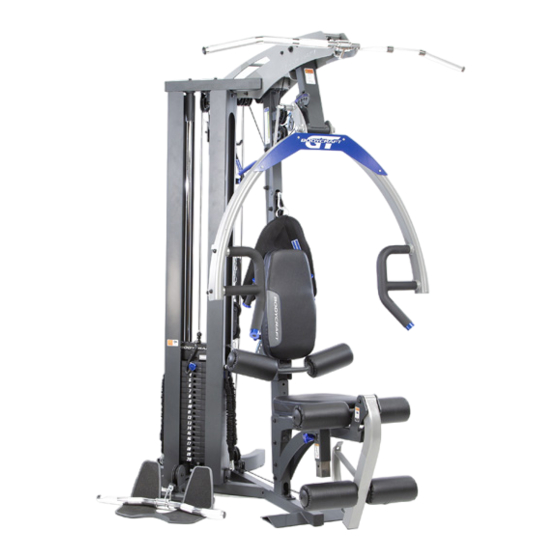
GT
Strength Training System
To see in
FULL COLOR
& additional information,
Open your Camera
scan this QR code.
App and point it at
the QR Code
Shown with Available Options:
GT-FCA (Functional Cable Arms),
GT-LP (Leg Press),
S-Trainer-1 (Speed Trainer)
See Page 10 for option details
Base Serial Number: _ _ _ _ _ _ _ _ _ _ _ _ _
Purchased Date: ___ / ___ / ______
Dealer's Name:__________________________
Please register your products at:
https://www.bodycraft.com/product-registration/
Owner's Manual
GT-X v1.2
1
Advertisement
Table of Contents

Related Manuals for Recreation Supply BodyCraft GT


Summary of Contents for Recreation Supply BodyCraft GT
- Page 1 Strength Training System To see in FULL COLOR & additional information, Open your Camera scan this QR code. App and point it at the QR Code Shown with Available Options: GT-FCA (Functional Cable Arms), GT-LP (Leg Press), S-Trainer-1 (Speed Trainer) See Page 10 for option details Base Serial Number: _ _ _ _ _ _ _ _ _ _ _ _ _ Purchased Date: ___ / ___ / ______...
- Page 2 This page intentionally left blank...
- Page 3 Please call your local dealer or BODYCRAFT. BODYCRAFT (a division of Recreation Supply, Inc.) 7699 Green Meadows Dr. Lewis Center, OH 43035...
-
Page 4: Table Of Contents
Table of Contents - GT 1 of 2 NOTE: When you have downloaded the Owner’s Manual into a PDF reader, go directly to the desired page by touching words in this Table of Contents. Product Safety Information Page Product Safety ……………………………………………………………... Important Notes, Recommended Tools &... - Page 5 Table of Contents - GT 2 of 2 NOTE: When you have downloaded the Owner’s Manual into a PDF reader, go directly to the desired page by touching words in this Table of Contents. Page Product Assembly - How to Assemble the GT STEP 10 - Adjust the Cables for Correct Tension …..……….……………...
-
Page 6: Product Safety
● Before beginning this or any other exercise program, consult your physician. This is especially important for individuals over the age of 35 or persons with preexisting health problems. Recreation Supply, Inc. assumes no responsibility for personal injury or property damage sustained by or through use of this product. -
Page 7: Important Notes, Recommended Tools & Cleaners
Important Notes, Recommended Tools & Cleaners , GT Important Notes and Tips: Before assembly, read all instructions thoroughly and preview diagrams to help make the installation easier. 2. Make sure all parts are accounted for and in proper condition before beginning assembly. See the parts list. -
Page 8: Warning Labels, Maintenance Schedule - Details
Warning Labels, Maintenance Schedule & Serial Number, GT Carefully read ALL warning, caution & maintenance schedule labels... - Page 9 Warning Labels, Maintenance Schedule & Serial Number Placement, GT / FCA / LP Carefully read ALL warning, caution & maintenance schedule labels...
-
Page 10: Product Overview Machine Options - Fca, Leg Press & S-Trainer
Machine Options, GT S-Trainer-1 Speed Trainer Option GT-LP Leg Press Option GT-FCA Functional Cable Arms Option To install the GT-FCA Functional Cable Arms Option, go directly to the GT Functional Cable Arms - Owner’s Manual for assembly instructions. To install the GT-LP Leg Press/Calf Option, go directly to the GT Leg Press... -
Page 11: Machine Dimensions, Room Layouts
Machine Dimensions & Room Layouts, GT Your BODYCRAFT GT Strength Training System was designed to be placed in a corner. Overall Dimensions 62.2”L 53.9”W x 82.4”H For additional Room Layouts on the GT Options go to: GT Leg Press - Owner’s... -
Page 12: Weight Ratios - Gt, Fca & Lp
Weight Stack Ratios, GT / FCA / LP 100% 200% 200% 300% 100% 100% 200% 300% 200% Bench Press with Doubler from the Functional Cable Arms 300% Leg Press with Hook attached for Turbo Feature... -
Page 13: Assembly Parts & Hardware List
Assembly Parts, GT 1 of 3 NOTE: For a complete service parts list, please refer to the detailed parts list & exploded view …………………………………….at the rear of this manual. Part # Assembly Parts List GT-X-001-ASM Frame, Bottom - Assembly w/ Serial # GT-X-002-ASM Frame, Connector, Top - Assembly GT-X-003-ASM Frame, Front, Upright - Assembly GT-X-004... - Page 14 Assembly Parts, GT 2 of 3 NOTE: For a complete service parts list, please refer to the detailed parts list & exploded view …………………………………….at the rear of this manual. Part # Assembly Parts List GT-X-041-ASM Adjustable Stopper, for the Adjustable Pulley Block - Assembly GT-X-043 Spacer Sleeve, between Pulleys P5 &...
- Page 15 Assembly Parts - Hardware, GT 3 of 3 Part # Assembly Hardware GT-X-083 Washer, Spring, 5/16" - BLK GT-X-084 Washer, Spring, 3/8" - BLK GT-X-085 Washer, Spring, 1/2" - BLK GT-X-086 Washer, Flat, Large, φ8mm - BLK GT-X-087 Washer, Flat, Large, φ10mm - BLK GT-X-088 Washer, Flat, 1/2"...
-
Page 16: Shipping Box & What's Inside
Shipping Boxes & What’s Inside Each One, GT Large Box 1 of 2 Net Weight: 160.3 lbs (72.7 KGS) Gross Weight: 185.6 lbs (84.2 KGS) Box Size: 46.3” W x 42.1” L x 11.6” H (1,175mm W x 1,070mm L x 295mm H) Medium Box 2 of 2 Net Weight: 131.4 lbs (59.6 KGS) -
Page 17: Pre-Assembly Tips
Product Assembly - Preassembly Tips - GT PREASSEMBLY TIP #1 – “Stage Right”. During the assembly process we will be stating Right, Left, Front, Back, Top, or Bottom. These all are in the perspective of the user in the machine facing outward with feet on the ground. See below images as examples. -
Page 18: Step 1 - Step 4
Product Assembly, GT, STEP 1a - 1b Please Hand Tighten All Nuts & Bolts Until STEP 2a TEP 1a - 1b: Install Uprights to Bottom & Top Frames View Keys Red dotted (large): Structural parts assembled direction. Red dotted (med): Sub-parts assembled direction. - Page 19 Product Assembly, GT, STEP 1c - 1d Please Hand Tighten All Nuts & Bolts Until STEP 2a TEP 1c: Install Foot Plate TEP 1d: Install Seat Support Frame The Longer Bolts 3/8" x 3-3/4" Part # Assembly Hardware GT-X-084 Washer, Spring, 3/8" - BLK GT-X-089 Washer, Flat, 3/8"...
- Page 20 Product Assembly, GT, STEP 2a - “Torque Time” STEP 2a: “Torque Time” on Main Frame Nuts & Bolts from STEP 1a - 1d NOTE: These recommended torque Example of being overtightened specs should be followed for correct not using the recommended assembly and safe operation of this torque specs.
- Page 21 Product Assembly, GT, STEP 2b TEP 2b: Install Back Pad Adjusting Frame & Pull Pin Note: Fully tighten until the gap is closed. Then loosen, up to 1/8 turn so that the Adjusting Frame (15) will move but has no play. Fully tighten Pop-Pin with Adjustable Wrench.
- Page 22 Product Assembly, GT, STEP 2c - DECISION POINT DECISION POINT GT - STEP 2c If you are only assembling a GT If you are simultaneously assembling the: Strength Training System at this time: GT Strength Training System Go to STEP 3a GT-FCA (GTX) Option Please go directly to the...
- Page 23 Product Assembly, GT, STEP 3a TEP 3a: Install Adjusting Seat Frame & Seat Pad Confirm spring washer then flat washer. 11-ASM TIP: Easier to install hardware when flipped upside down. 8 ft-lbs (+/- 1 lbs) Recommended Tools: TORQUE WRENCH w/ 9/16 SOCKET &...
- Page 24 Product Assembly, GT, STEP 3b TEP 3b: Leg Extension Arm & Knee Hold Down Frame 15 ft-lbs (+/- 2 lbs) Screw, spring washer then flat washer. Flat notch through right side to left side. 13-ASM 12 ft-lbs (+/- 1 lbs) Fully tighten at this time all hardware to the Recommended Torque Specs Part #...
- Page 25 Product Assembly, GT, DECISION POINT on STEP 3c DECISION POINT GT - STEP 3c At the Leg Extension / Curl Station, the bottom set of Rollers (51) can be installed at either hole on the Leg Extension Arm (13-ASM). The Support Tube (50) can be installed in: The top hole, which will accommodate shorter legs.
- Page 26 Product Assembly, GT, STEP 3d TEP 3d: Install Support Tubes & Rollers 3 ft-lbs (+/- 0.5 lbs) Confirm washer is behind plastic cover. 8 ft-lbs (+/- 1 lbs) Measure to center Support Tubes Fully tighten at this time to the Recommended Torque Specs Part # Assembly Parts List...
- Page 27 Product Assembly, GT, STEP 4a - 4b TEP 4a - 4b: Install the Connecting Frame & Back Pad 15 ft-lbs (+/- 2 lbs) TIP: Preassemble one 8 ft-lbs side of the Metal Hinge (+/- 1 lbs) to the Seat Back, then slide onto the Adjusting Frame.
- Page 28 Product Assembly, GT, STEP 4c TEP 4c: Install the Press Arm Assembly 3 ft-lbs (+/- 0.5 lbs) Recommended Tools 5/16” ALLEN WRENCH RUBBER MALLET CAUTION: Press Arm Assembly (7-ASM) is large and awkward to install, especially to the Connecting Frame (16-ASM). Find a friend to help with STEP 4b to ensure a happier and longer life during the rest of the assembly process! Part # Assembly Parts List...
-
Page 29: Step 5 - Weight Stack W/ Optional 200 Lbs Stack
Product Assembly, GT, STEP 5a - 5b STEP 5a Please ONLY Hand Tighten the Guide Rods, No Tools TEP 5a: Install Guide Rods DO NOT USE Pliers or Locking Jaw Pliers TEP 5b: Install Selector Rod Guide Rods have welded-in CONFIRM the Large Spacer nuts and will need to be Washers are placed on the Main... - Page 30 Product Assembly, GT, STEP 5c - DECISION POINT DECISION POINT 150 lb GT - STEP 5c Weight Stack OPTIONAL 200 lb If you are installing the 150 lb Weight Weight Stack Stack, use the 7” tall Stack Spacers (22). If you are installing the OPTIONAL 200 lb Weight Stack, use the 3”...
- Page 31 Product Assembly, GT, STEP 5d - 5e CRITICAL: Align the selector holes on the weight plates forward, toward the front of the machine, with the half moon opening facing down. Confirm back side of weight stack should have NO holes showing. See image above. TEP 5d: Lightly Lube Guide Rods NOTE: Lightly lubing the Guide Rods is a great practice to do at this point due to:...
- Page 32 Product Assembly, GT, STEP 5f TEP 5f: Install Limit Tubes & Top Connector Frame 17 ft-lbs (+/- 2 lbs) 20 ft-lbs (+/- 2 lbs) 3/8 x 3-1/4 1/2 x 5-1/4 Recommended Tools: TORQUE WRENCH w/ 3/4, 9/16 SOCKETS & 3/4, 9/16 WRENCHES Part # Assembly Hardware Tighten to the Recommended...
-
Page 33: Step 6 - Top Cable #36
Product Assembly, GT, STEP 6 Top Cable #36 - OVERVIEW 1 of 2 Top Cable #36 4,830mm (190.16") L 3-1/2” Pulleys P1 - P12 Pulleys are numbered GREEN circles for installation routing. NOTE: Actual color of Top Cable #36 is black. Shown in the assembly STEPS in ORANGE for easy viewing... - Page 34 Product Assembly, GT, STEP 6 Top Cable #36 OVERVIEW 2 of 2 Top Cable #36 4,830mm (190.16") L 3-1/2” Pulleys P1 - P12 Pulleys are numbered GREEN circles for installation routing. NOTE: Actual color of Top Cable #36 is black. Shown in the assembly STEPS in ORANGE for easy viewing...
- Page 35 Product Assembly, GT, STEP 6a & Optional Speed Trainer Recommended Tool TEP 6a: Install Top Cable #36 to Top Plate ADJUSTABLE WRENCH Tighten the Cable Bolt & Jam Nut at this time. Part # Assembly Parts List GT-X-036 Cable, Top, 4,830mm (190.16") L GT-X-119 Selector Pin w/ Lanyard, Aluminum - BLUE OPTIONAL Speed Trainer...
- Page 36 Product Assembly, GT, STEP 6b - 6c & DECISION POINT Please Hand Tighten All Nuts & Bolts Until STEP 6n TEP 6b: Install Pulley P1 Recommended Tool ADJUSTABLE WRENCH Screw in Threaded Rod or Adjustable Stopper 50% into the Upper Frame. Tighten the Jam Nut at this time.
- Page 37 Product Assembly, GT, STEP 6d - 6e TEP 6d: Install Pulley P3 Please Hand Tighten All Nuts & Bolts Until STEP 6n TEP 6e: Install Adjustable Stopper, Double Pulley Block & Pulley P4 Part # Assembly Parts List GT-X-017 Pulley Block, Double, Closed Flat End, Adjustable w/ 13 each GT-X-041-ASM Adjustable Stopper, for the Adjustable Pulley Block - Assembly GT-X-068 Pulley, 90mm (3-1/2") x δ26mm ID...
- Page 38 Product Assembly, GT, STEP 6f - 6g Please Hand Tighten All Nuts & Bolts Until STEP 6n TEP 6f - 6g: Install Pulleys P5 - P6 Part # Assembly Parts List GT-X-068 Pulley, 90mm (3-1/2") x δ26mm ID Bushing, Plastic, for Pulley to Frame, GT-X-076 3/8"...
- Page 39 Product Assembly, GT, STEP 6h - 6i Please Hand Tighten All Nuts & Bolts Until STEP 6n TEP 6h - 6i: Install Pulleys P7 - P8 Part # Assembly Parts List GT-X-068 Pulley, 90mm (3-1/2") x δ26mm ID Part # Assembly Hardware GT-X-089 Washer, Flat, 3/8"...
- Page 40 Product Assembly, GT, STEP 6j - 6k Please Hand Tighten All Nuts & Bolts Until STEP 6n TEP 6j - 6k: Install Pulleys P9 - P10 Part # Assembly Parts List GT-X-068 Pulley, 90mm (3-1/2") x δ26mm ID Part # Assembly Hardware GT-X-089 Washer, Flat, 3/8"...
- Page 41 Product Assembly, GT, STEP 6l - 6m Please Hand Tighten All Nuts & Bolts Until STEP 6n TEP 6l - 6m: Install Pulleys P11 - P12 Part # Assembly Parts List GT-X-068 Pulley, 90mm (3-1/2") x δ26mm ID Part # Assembly Hardware GT-X-089 Washer, Flat, 3/8"...
- Page 42 Product Assembly, GT , STEP 6n - “Torque Time” 17 ft-lbs STEP 6n: “Torque Time” (+/- 2 lbs) ● Tighten all 3/8” Bolts from STEPS 6b to 6m to the recommended torque specs of 17 ft-lbs (+/- 2 lbs) Recommended Tools: 17 ft-lbs TORQUE WRENCH w/ 9/16 SOCKET (+/- 2 lbs)
-
Page 43: Step 7 - Ab Crunch Cable #37
Product Assembly, GT, STEP 7 (Ab Cable #37) OVERVIEW Ab Crunch Cable #37 4,230mm (166.5") L 3-1/2” Pulleys P14 - P18 Pulleys are numbered GREEN circles for installation routing. 4-1/2” Pulley P13 Pulleys are numbered GREEN circles for installation routing. NOTE: Actual color of Ab Cable #37 is black. - Page 44 Product Assembly, GT, DECISION POINT & STEP 7a - 7b TEP 7a - 7b: Install Ab Crunch Cable #37 and Pulleys P13 - P14 If you are simultaneously assembling the: GT Strength Training System GT-FCA (GTX) Option Please go directly to the GT-FCA (GTX) Owner’s Manual to continue the assembly GT-FCA (GTX),...
- Page 45 Product Assembly, GT, STEP 7c - 7d Please Hand Tighten All Nuts & Bolts Until STEP 7h TEP 7c: Install Pulley P15 NOTE: Easier to install the Spacer Sleeve #43, if done in this order. TEP 7d: Install Pulley P16 & Spacer Sleeve #43 Part # Assembly Parts List Spacer Sleeve, between Pulleys P5 &...
- Page 46 Product Assembly, GT, STEP 7e - 7g Please Hand Tighten All Nuts & Bolts Until STEP 7h TEP 7e - 7f: Install Pulleys P17 - P18 TEP 7g : Install Cable to Main Frame (1-ASM) Part # Assembly Parts List GT-X-068 Pulley, 90mm (3-1/2") x δ26mm ID GT-X-071...
- Page 47 Product Assembly, GT, STEP 7h - “Torque Time” STEP 7h: “Torque Time” ● Tighten all 3/8” Bolts from STEP 7a - 7f to the recommended torque specs of 17 ft-lbs (+/- 2 lbs) Recommended Tools: 17 ft-lbs (+/- 2 lbs) TORQUE WRENCH w/ 9/16 SOCKET &...
-
Page 48: Step 8 - Lower Cable #38
Product Assembly, GT, STEP 8 (Lower Cable #38) OVERVIEW Lower Cable #38 3,080mm (121.25") L 3-1/2” Pulleys P19 - P23 Pulleys are numbered GREEN circles for installation routing. NOTE: Actual color of Lower Cable #38 is black. Shown in the assembly STEPS in ORANGE for easy viewing... - Page 49 Product Assembly, GT, STEP 8a - 8b Please Hand Tighten All Nuts & Bolts Until STEP 8g TEP 8a - 8b: Install Lower Cable #38 and Pulleys P19 - P20 Part # Assembly Parts List GT-X-038 Cable, Lower, 3,080mm (121.25") L GT-X-068 Pulley, 90mm (3-1/2") x δ26mm ID Part #...
- Page 50 Product Assembly, GT, STEP 8c - 8e Please Hand Tighten All Nuts & Bolts Until STEP 8g TEP 8c: Install Pulley P21 TEP 8d - 8e: Install Pulleys P22 - P23 Part # Assembly Hardware GT-X-089 Washer, Flat, 3/8" - BLK Part # Assembly Parts List GT-X-102...
- Page 51 Product Assembly, GT, STEP 8f & 8g - “Torque Time” TEP 8f: Install Cable Ball End to Leg Ext. Arm STEP 8g: “Torque Time” ● Tighten all 3/8” Bolts from STEP 8a - 8e to the recommended torque specs of 17 ft-lbs (+/- 2 lbs) 17 ft-lbs (+/- 2 lbs) 17 ft-lbs...
-
Page 52: Step 9A - Final Assembly Lube Guide Rods
Product Assembly, GT, STEP 9a - Final Assembly Lube Guide Rods STEP 9a : Lube both Guide Rods (6) with 100% pure Silicone Lube or Teflon PTFE Grease. ONLY apply a light layer with a clean rag. Then do a set of reps with low weights to spread the lubricant thoroughly the Guide Rods (6). -
Page 53: Step 9B - Weight Stack Covers & Accessories
Product Assembly, GT, STEP 9b w/ Accessory Placement Locations TEP 9b: Install Weight Stack Shroud Covers & Accessories Recommended Tools: TORQUE WRENCH w/ 5 ft-lbs 3/16. Hex Bit Socket (+/- 0.5 lbs) Tighten to the Recommended Torque Specs at this time. 5/16 x 1/2 Part # Assembly Parts List... -
Page 54: Step 9C - Optional Speed Trainer
Product Assembly, GT, STEP 9c - Optional Speed Trainer TEP 9c: Installing the OPTIONAL Speed Trainer Use the longer Hex Head 5/16 x 3/4 Bolt #404 Recommended Tools: TORQUE WRENCH w/ 1/2 SOCKET Tighten to the Recommended Torque Specs at this time. 5 ft-lbs (+/- 0.5 lbs) Part #... -
Page 55: Step 10: Adjust The Cables For Correct Tension
Product Assembly, GT, STEP 10 - Adjust the Cables for Correct Tension TEP 10: Adjust the Cables for Correct Tension The Cables should be tightened to the point just before the Top Plate lifts off the stack. See below for Major Adjustments or Fine Adjustment for correct cable adjustments. -
Page 56: Step 11 - Weight Stack Stickers Installation
Product Assembly, GT, STEP 11 - Weight Stack Stickers Installation... -
Page 57: Step 12 - Final Assembly Lube, Clean Up, & Polish
Product Assembly, GT, STEP 12 - Final Assembly Clean up, Lube & Polish STEP 12a: Remove all Assembly Stickers, i.e. Part Numbers & Right / Left Circles ● Easy to remove with fingernail or plastic scraper ● If adhesive residue is on frame: ○... -
Page 58: Maintenance & Repairs Routine Schedule
Product Assembly, Routine Schedule, GT... -
Page 59: General & Cable Inspections
Product Assembly, General & Cable Inspection, GT... -
Page 60: Lubrication Maintenance
Product Assembly, Lubrication Maintenance, GT... -
Page 61: Strength Cable Wear Indicators
Product Assembly, Strength Cable Wear Indicators, GT... -
Page 62: Detailed Parts Exploded View
Detailed Parts, Exploded View, GT 1 of 3 3-1/2 3-1/2 3-1/2 3-1/2 3-1/2 Top Frame w/ Pulley Locations 3-1/2 Top Frame w/ Pulleys Internal View Single Closed Pulley Block 3-1/2 Rear Upright 3-1/2 3-1/2 Frame 3-1/2 4-1/2 * The Larger Pulley Front Upright GT - Structural Frames Frame w/ Pulleys... - Page 63 Detailed Parts, Exploded View, GT 2 of 3 112 90 60 72 16 3-1/2 3-1/2 Press Arm w/ Connection Frame Adjusting & Knee Hold Down Frames w/ Pad/Rollers 9-ASM 10-ASM GT - Structural Frames Assembled * Shown without pulleys Adjusting Frame for Seat Pad &...
- Page 64 Detailed Parts, Exploded View, GT 3 of 3 1/2 Bolts #98 from Top Frame #4 Accessories 89 115 3-1/2 89 115 3-1/2 83 90 Weight Stack w/ Connector Frame GT - Structural Frames Assembled * Shown without pulleys Cables 83 90 4,830mm (190.16") L 4,230mm (166.5") L - 5 each extra plates #118...
-
Page 65: Detailed Parts List
Detailed Parts List - GT 1 of 4 Part # Detailed Parts list GT-X-001 Frame, Bottom GT-X-002 Frame, Connector, Top GT-X-003 Frame, Front, Upright GT-X-004 Frame, Top GT-X-005 Frame, Rear, Upright Guide Rod, 1" OD x 72-1/2" L, 3/8" nuts inserted & welded both GT-X-006 ends GT-X-007... - Page 66 Detailed Parts List - GT 2 of 4 Part # Detailed Parts list GT-X-036 Cable, Top, 4,830mm (190.16") L GT-X-037 Cable, Ab Crunch, 4,230mm (166.5") L GT-X-038 Cable, Lower, 3,080mm (121.25") L GT-X-039 End Cap, Aluminum - BLUE Threaded Rod, between Top Connector Frame & Single Block GT-X-040 Pulley (Not used with FCA) GT-X-041...
- Page 67 Detailed Parts List - GT 3 of 4 Part # Detailed Parts list GT-X-077 Bushing, Steel, for Upper Pulleys & Press Arm, 20mm ID GT-X-078 Connecting Chain Link GT-X-079 Snap Hook GT-X-080 Accessory, Chain, 19" L GT-X-081 Sticker, Weight Stack 1 - 20 GT-X-082 Washer, Spring, φ5mm - Stainless Steel GT-X-083...
- Page 68 Detailed Parts List - GT 4 of 4 Part # Detailed Parts list GT-X-120 Silicone Lube Bottle, for Guide Rods GT-X-121 Poster - Exercise Guide for GT Strength Training System GT-X-122 Warning Label - Master Rules and Precautions - v1.6v GT-X-123 Warning Label - Pinch Point, Vertical- v1.6 GT-X-124...
-
Page 69: Required Info Before Initiating A Service Case
Service Request Required Information BEFORE Initiating a Service Case The following information is needed to help expedite troubleshooting and to ensure the correct part(s) are sent if needed for a repair: What product / model # do you have? Unit serial number? Installed by a dealer or direct sale? Date of installation? Date of service issue? -
Page 70: Product Warranty
Product Warranty - Strength VALID FOR USA AND CANADA ONLY (Please consult with your local distributor for warranty info specific to your region). BODYCRAFT warrants its products to be free of defects in materials and workmanship for the time stated below to the original purchaser. -
Page 71: Product Warranty Registration
Warranty Registration - Strength Thank you for purchasing a BODYCRAFT product. To validate the product warranty the fast and easy way, please go on-line now to https://www.bodycraft.com/product-registration.html register your product. The information you provide will never be distributed to any other individuals or agencies for any purpose.
Need help?
Do you have a question about the BodyCraft GT and is the answer not in the manual?
Questions and answers