Table of Contents
Advertisement
Quick Links
Advertisement
Table of Contents

Subscribe to Our Youtube Channel
Related Manuals for Apogee SI-411


Summary of Contents for Apogee SI-411
- Page 1 OWNER’S MANUAL INFRARED RADIOMETERS Models: SI-411, SI-421, SI-431, SI-4H1 APOGEE INSTRUMENTS, INC. 721 WEST 1800 NORTH, LOGAN, UTAH 84321, USA TEL: (435) 792-4700 FAX: (435) 787-8268 WEB: APOGEEINSTRUMENTS.COM Copyright © 2013 Apogee Instruments, Inc.
-
Page 2: Table Of Contents
TABLE OF CONTENTS DECLARATION OF CONFORMITY……………………………..……………………. 3 INTRODUCTION…………………………………………………………………………….. 4 SENSOR MODELS............... 5 SPECIFICATIONS……………………………………………………………………………. 6 DEPLOYMENT AND INSTALLATION……………………………………………….. 8 OPERATION AND MEASUREMENT……………………………………..…………. 10 MAINTENANCE AND RECALIBRATION…………………………………..17 TROUBLESHOOTING AND CUSTOMER SUPPORT…………………………… 18 RETURN POLICY AND WARRANTY…………………………………………………. 19... -
Page 3: Declaration Of Conformity
(PBB), polybrominated diphenyls (PBDE). Further note that Apogee Instruments does not specifically run any analysis on our raw materials or end products for the presence of these substances, but rely on the information provided to us by our material suppliers. -
Page 4: Introduction
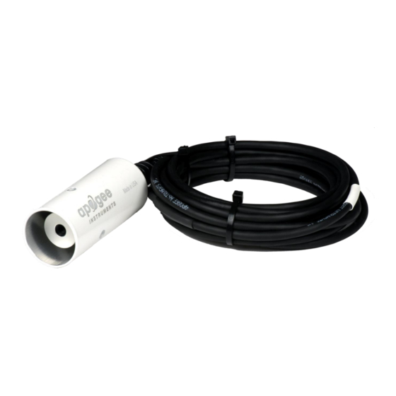
(soil, vegetation, water, snow) temperature measurement in energy balance studies. Apogee Instruments SI series infrared radiometers consist of a thermopile detector, germanium filter, precision thermistor (for detector reference temperature measurement), and signal processing circuitry mounted in an anodized aluminum housing, and a cable to connect the sensor to a measurement device. -
Page 5: Sensor Models
SENSOR MODELS Apogee SI series infrared radiometer models covered in this manual, SI-400 series, are digital versions that provide an SDI-12 output. Analog models with a voltage output are also available; see manual for SI- 100 series infrared radiometers. Sensor model number, serial number, and production date are located on a label near the pigtail leads on the sensor cable. -
Page 6: Specifications
Response Time: 0.6 s, time for detector signal to reach 95 % following a step change; fastest data transmission rate for SDI-12 circuitry is 1 s Field of View: 22° half angle (SI-411) 18° half angle (SI-421) 14° half angle (SI-431) 32°... - Page 7 Calibration Traceability: Apogee SI series infrared radiometers are calibrated to the temperature of a custom blackbody cone held at multiple fixed temperatures over a range of radiometer (detector/sensor body) temperatures. The temperature of the blackbody cone is measured with replicate precision thermistors thermally bonded to the cone surface.
-
Page 8: Deployment And Installation
The green cap can be used as a protective covering for the sensor, when it is not in use. An Apogee Instruments model AM-210 mounting bracket is recommended for mounting the sensor to a cross arm or pole. The AM-210 allows adjustment of the angle of the sensor with respect to the target... - Page 9 Different mounting geometries (distance and angle combinations) produce different target shapes and areas, as shown below. A simple FOV calculator for determining target dimensions based on infrared radiometer model, mounting height, and mounting angle, is available on the Apogee website: http://www.apogeeinstruments.com/using-your-apogee-instruments-infrared-radiometer/.
-
Page 10: Operation And Measurement
SDI-12 functionality that includes the M or C command. Wiring: All Apogee SDI-12 infrared radiometer models (SI-400 series) have sensor-specific calibration coefficients determined during the custom calibration process. Coefficients are programmed into the microcontroller at the factory. Calibration data for each sensor are provided on a calibration certificate (shown on... - Page 11 Apogee SI series infrared radiometers are calibrated in a temperature controlled chamber that houses a custom-built blackbody cone (target) for the radiation source. During calibration, infrared radiometers (detectors) are held in a fixture at the opening of the blackbody cone, but are thermally insulated from the cone.
- Page 12 “!”. SDI-12 language supports a variety of commands. Supported commands for the Apogee Instruments SI-400 series infrared radiometers are listed in the following table (“a” is the sensor address. The following ASCII Characters are valid addresses: “0-9” or “A-Z”).
- Page 13 executed. M commands are shown in the following examples: Command Response Response to 0D0! a0011<cr><lf> Target Temperature aM1! a0012<cr><lf> Target Temperature and Sensor Body Temperature aMC! a0011<cr><lf> Target Temperature w/ CRC aMC1! a0012<cr><lf> Target Temperature and Sensor Body Temperature w/ CRC where a is the sensor address (“0-9”, “A-Z”, “a-z”) and M is an upper-case ASCII character.
- Page 14 sensors with the factory address of 0 requires changing the address on one of the sensors to a non-zero value in order for both sensors to communicate properly on the same channel: Command Response Description aAn! n<cr><lf> Change the address of the sensor where a is the current (old) sensor address (“0-9”, “A-Z”), A is an upper-case ASCII character denoting the instruction for changing the address, n is the new sensor address to be programmed (“0-9”, “A-Z”), and !
- Page 15 ⋅ ⋅ Where C2, C1, and C0 are the custom calibration coefficients listed on the calibration certificate (shown above) that comes with each SI-100 series radiometer (there are two sets of polynomial coefficients, one set for m and one set for b). Note that T is converted from Kelvin to Celsius (temperature in C equals temperature in K minus 273.15) before m and b are plotted versus T To make measurements of target temperatures, Eq.
- Page 16 Rearrangement of Eq. (2) to solve for T yields the equation used to calculate the actual target surface Target temperature (i.e., measured brightness temperature corrected for emissivity effects): − − ε ⋅ Sensor Background ε Equations (1)-(3) assume an infinite waveband for radiation emission and constant ε at all wavelengths. These assumptions are not valid because infrared radiometers do not have infinite wavebands, as most correspond to the atmospheric window of 8-14 µm, and ε...
-
Page 17: Maintenance And Recalibration
The solvent should be allowed to do the cleaning, not mechanical force. It is recommended that infrared radiometers be recalibrated every two years. See the Apogee webpage for details regarding return of sensors for recalibration (http://www.apogeeinstruments.com/tech-... -
Page 18: Troubleshooting And Customer Support
Compatible Measurement Devices (Dataloggers/Controllers/Meters): Any datalogger or meter with SDI-12 functionality that includes the M or C command. An example datalogger program for Campbell Scientific dataloggers can be found on the Apogee webpage at http://www.apogeeinstruments.com/content/Infrared-Radiometer-Digital.CR1. Modifying Cable Length: SDI-12 protocol limits cable length to 60 meters. -
Page 19: Return Policy And Warranty
RETURN AND WARRANTY POLICY RETURN POLICY Apogee Instruments will accept returns within 30 days of purchase as long as the product is in new condition (to be determined by Apogee). Returns are subject to a 10 % restocking fee. WARRANTY POLICY... - Page 20 5. Upon receipt, Apogee Instruments will determine the cause of failure. If the product is found to be defective in terms of operation to the published specifications due to a failure of product materials or craftsmanship, Apogee Instruments will repair or replace the items free of charge.
Need help?
Do you have a question about the SI-411 and is the answer not in the manual?
Questions and answers