
Related Manuals for Kofloc 8700 Series


Summary of Contents for Kofloc 8700 Series
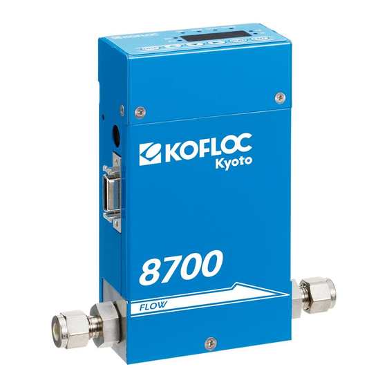
- Page 1 MJ400307A1 Thermal Mass Flow Meter / Controller MODEL 8700 SERIES RS-485 Communications Instruction Manual...
-
Page 2: Table Of Contents
MJ400307A1 Table of Contents Page 1. Foreword 2. RS-485 Communication Specifications 3. Example of Connection 4. How to Enable the RS485 Communication Terminator 5. List of Communication Commands and Addresses 6-14 6. Operation-Confirmed Converter for PC... -
Page 3: Foreword
MJ400307A1 1.Foreword This document describes the specifications and operation of the RS-485 communications function installed as a standard feature in Model 8700. The wiring, installation and operating procedures, other than communications, are presented in a separate instruction manual. Prior to use, please read it also. 2.RS-485 Communication Specifications Item Specifications... -
Page 4: Example Of Connection
MJ400307A1 3.Example of Connection An example (reference) of wire connection is shown below. In the following example, the terminator is turned on in Communication controller Model 8700 (ID=n). Max. 100m ation Communic controller A Model 8700 Model 8700 Model 8700 ID=1 ID=2 ID=n... -
Page 5: How To Enable The Rs485 Communication Terminator
MJ400307A1 4.How to Enable the RS485 Communication Terminator This equipment incorporates an RS485 terminator (120 Ω ). When the equipment is shipped, it has not been enabled. Where it is considered that communications are disturbed by reflective noise, etc., conduct an operation to enable the terminator as explained below. -
Page 6: List Of Communication Commands And Addresses
MJ400307A1 5.List of Communication Commands and Addresses ◆Command messages ① Byte read Command Checksum Equipment ID Address ② Word read Command Checksum Equipment ID Address ③ Byte write Command Separator Equipment ID Address Write data Checksum ④ Word write Command Separator Equipment ID Address... - Page 7 MJ400307A1 ◆Normal/abnormal response messages ① Byte read Command Exit code Equipment ID Address Read data Sign Checksum ② Word read Command Exit code Equipment ID Address Read data Sign Checksum ③ Byte write Command Exit code Equipment ID Address Checksum ④...
- Page 8 MJ400307A1 ◆Detailed explanation ①STX Indicates the head of the message. Fixed to 02H. When STX is received, the equipment unconditionally judges it is the first letter of the message. ②Equipment ID Specify the destination equipment ID (1 – 127). ③Command A command to the equipment.
- Page 9 MJ400307A1 ⑨CR and LF Indicate the end of the message. CR fixed “0DH” and LF fixed to “0AH”. ◆Data address ※Since EEPROM has a limit of the time of rewriting, use RAM if the rewriteing will be done frequently, and use EEPROM if the data will be retained when the power is turned off. ※In case of the rewriting to EEPROM, it will be reflected in action when the power is turned on again.
- Page 10 MJ400307A1 EEPROM Indication Data Range Size Add. Add. RUN key 00: RUN key not used Byte 1101 ○ ○ 4101 ○ ○ 01: RUN key used (d-07) action selection Flow rate 00: Digital setting Byte 1102 ○ ○ 4102 ○ ○...
- Page 11 MJ400307A1 EEPROM Indication Data Range Add. Add. 0:Not used 1:Only upper limit alarm used 1109 ○ ○ 4109 ○ ○ Flow rate alarm set type 2: Only lower limit alarm used 3:Upper/lower alarms used 0:Control continue & alarm output Selection of action when normally on 1110 ○...
- Page 12 MJ400307A1 ③ Function setting mode (parameter) data EEPROM Indication Data Range Add. Add. 1200 4200 Flow rate OK judgment ○ ○ ○ ○ 5~1000 (0.5%~100.0% FS) 1201 4201 range 1204 4204 Flow rate deviation upper ○ ○ ○ ○ 5~1000 (0.5sec~100.0sec) 1205 4205 limit alarm value...
- Page 13 MJ400307A1 EEPROM Indication Data Range Add. Add. 1222 4222 PV forced zero function ○ ○ ○ ○ 0~9999 (0.0sec~999.0sec) 1223 4223 delay time 1224 4224 ○ ○ ○ ○ 0~1000 (0.0%~100.0% FS) SP upper limit flow rate 1225 4225 1226 4226 ○...
-
Page 14: Operation-Confirmed Converter For Pc
MJ400307A1 ⑤ Integrated flow rate data EEPROM Indication Data Range Add. Add. 1400 4400 Integrated flow rate (lower ○ × × × 0~9999 1401 4401 4 digits) 1402 4402 Integrated flow rate (middle ○ × × × 0~9999 1403 4403 4 digits) 1404 4404... - Page 15 MJ400307A1 URL:http:// www.kofloc.co.jp...
Need help?
Do you have a question about the 8700 Series and is the answer not in the manual?
Questions and answers