
Related Manuals for Flexit CI 70


Summary of Contents for Flexit CI 70
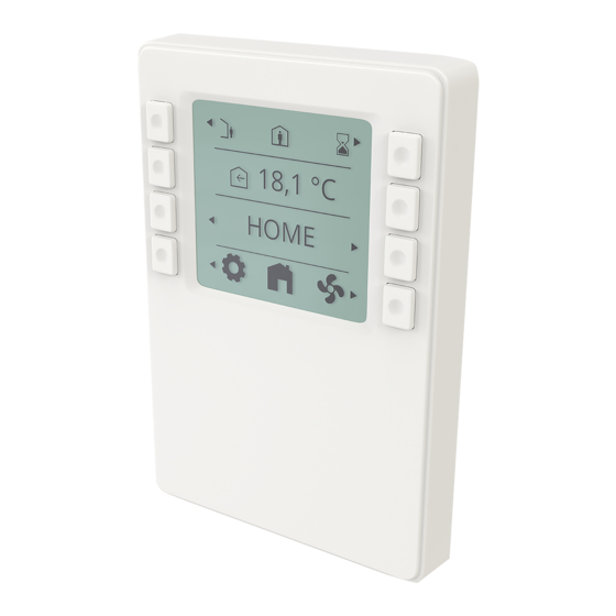
- Page 1 116081EN-07 2023-02 CI 70 Flexit ART.NR. 116402 ASSEMBLY AND USER INSTRUCTIONS Control panel...
- Page 2 C I 7 0 Our products are subject to continuous development and we therefore reserve the right to make changes. We also disclaim liability for any printing errors that may occur.
-
Page 3: Table Of Contents
Contents Scope ..........................4 Mechanical design ......................4 2.1. Mounting .......................... 5 Icon description ......................8 3.1. Status icon description: ....................9 Sleep page & home page description ..............10 4.1. Layer consept .......................11 Settings ........................11 5.1. General description ....................11 5.2. Adjust time date & scheduler ...................12 5.3. -
Page 4: Scope
C I 7 0 1. Scope • The CI 70 works together with all ventilation units in the Nordic series • The CI 70 operates control functions, such as fan and temperature control • The CI 70 communicates with 2-wire interface to the controller through KNX PL-Link 2. -
Page 5: Mounting
2.1. MOUNTING The cable to the CI 70 control panel must be at least 30 cm from the 230 V cable (including dimmers, thermostats, etc.). Power cables must cross the CI 70 signal cable at a right angle. For concealed installation, the cable is laid in 16 mm cable tubes. - Page 6 C I 7 0 Min. 3 mm screwdriver SEAL...
- Page 7 h>20 mm A6V10733771M05 2- 52 81.4 [mm] Connector Pin Description KNX PL-Link (positive) KNX PL-Link (negative) + brown cord - white cord NOTICE! Installer can choose either pair of the pins to connect. Wires are NOT interchangeable! A6V10733771M07 The device is protected against faulty wiring, but communications does not work on interchanged wires.
-
Page 8: Icon Description
C I 7 0 3. Icon description AUTO MODE TIMER MODE HOME PAGE ELECTRICAL HEATER ENABLED ELECTRICAL HEATER DISABLED AWAY MODE HOME MODE GO BACK HIGH MODE ALARM FIRE PLACE MODE ALARM – NOT ACKNOWLEDGED COOKER HOOD MODE ALARM – ACKNOWLEDGED SUPPLY AIR NORMAL - ACKNOWLEDGED EXHAUST AIR... -
Page 9: Status Icon Description
3.1. STATUS ICON DESCRIPTION: Status icons max 3 icons at one time Position 1 Icon position ALARM ALARM – NOT ACKNOWLEDGED ALARM – ACKNOWLEDGED NORMAL - ACKNOWLEDGED BUT NOT RESETED SERVICE REQUEST SERVICE – NOT ACKNOWLEDGED 20°C SERVICE – ACKNOWLEDEGED AUTO MODE HOME Position 2... -
Page 10: Sleep Page & Home
C I 7 0 4. Sleep page & home page description Displays the room temperature at the panel. NB. If the panel is 20.1°C indoor temperature elsewhere. 16:25 Display actual time. Sleep page Display returns to sleep page after no usage in 4,0 min. 18.1°C Display supply air temperature setpoint according to operating mode. -
Page 11: Layer Consept
4.1. LAYER CONSEPT Screens/views are prioritized according to use cases. When screen with higher prio is called/activated it will be the dominant one. 1234 27 MIN A-alarm layer – high prio HIGH COOKER 18.1°C Special operation layer – medium prio HOME Basic layer –... -
Page 12: Adjust Time Date & Scheduler
C I 7 0 5.2. ADJUST TIME DATE & SCHEDULER 16:25 16:25 18.1°C HOME 31.01.1900 01.01.2000 Home page General Adjust time and date Adjust time: Press the arrows beside the clock: <- to reduce and -> to increase the time. Hold down to move faster. Adjust the date: Press the arrows beside the date: <- to reduce and ->... -
Page 13: Fan Speeds
5.3. FAN SPEEDS mode selection 18.1°C supply fan adjustment HOME exhaust fan adjustment Home page Fan speed NB. The fan speeds are factory-set to: Away 50%, Home 75% and High 100%. High must always be set higher than Home, which must be set higher than Away. -
Page 14: Fan Speed Setting Page
C I 7 0 5.3.1. Fan speed setting page Press of button 5 will change the views in loop towards right. Press of button 1 will change the views in reverse order - loop towards left. -
Page 15: Supply Air Temperatures
5.4. SUPPLY AIR TEMPERATURES mode selection 18.1°C supply air temperature adjustment electrical heater ENABLE/DISABLE Supply air HOME/AWAY adjustments 18.1°C 16.1°C Time delay setting when switching to 30 min AWAY mode with button 1. Supply air Supply air Home Away 5.4.1. Home page – mode selection 18.1°C HOME 18.1°C... -
Page 16: Home Page - Home/Away Selection
C I 7 0 5.4.2. Home page – home/away selection 18.1°C HOME 16.1°C 18.1°C AWAY HOME Away mode Home mode 5.4.3. Home page – in scheduler mode scheduler mode (time program) 18.1°C HOME 18.1°C 18.1°C 16.1°C HOME HIGH AWAY Home speed mode High speed mode Away mode... -
Page 17: Timer Functions
5.4.4. Timer functions 18.1°C 30 min 30 min HOME HIGH FIRE Home page High Fire place returns to HOME PAGE after 27 min prolongation time is elapsed HIGH returns to HOME PAGE if function is canceled If activated 5.5. INFORMATION Activation of cooker hood function via Digital input or wireless accesorie. -
Page 18: Alarm
C I 7 0 5.6. ALARM In case of alarm, the display will start to blink, and the appearance of the information will depend on alarm class, according to the pictures below. Error code 20.1°C 16:25 B-alarm A-alarm 5.6.1. Alarm mode 18.1°C HOME keep both buttons pressed... -
Page 19: Filter Alarm
5.6.2. Filter alarm in the unit have been replaced, follow the procedure, (section 5.6.3) and the alarm. (section 5.6.4) 5.6.3. alarm has appeared. NB! In case you can’t locate parameter P41 on your product, this functionality is not available. Please go procedure. -
Page 20: Acknowledge And Reset A-Alarm
C I 7 0 5.6.6. Acknowledge and reset A-alarm 5.6.7. Acknowledge B-alarm In case of critical A-alarms, application operation is Application is still operational (as much as possible), locked until alarm is acknowledged and reset. alarm has to be acknowledged. 18.1°C 18.1°C No alarms... -
Page 21: Alarm Codes
5.6.8. Alarm codes Error code Error source 1000…1999 Hardware related errors 2000…2999 Application related errors 3000…3999 Communication errors 5.6.9. Alarm codes – Hardware related errors Code # A/B-Alarm Name/Text 1000...1999 Code range for - Hardware 1001 B1 - Supply air temperature sensor fault 1002 B6 - Exhaust air temperature sensor fault 1003... -
Page 22: Expert Mode
C I 7 0 5.7. EXPERT MODE 5.7.1. Read parameter mode 18.1°C HOME Home page No active alarms No active service ---- ---- value [unit]... -
Page 23: Parameter List
5.7.2. Parameter list Parameter Description Unit Actual value Temperature sensor B4 °C Temperature sensor B8 °C Temperature sensor B5 °C Temperature sensor B1 °C Temperature sensor B3 °C Temperature sensor B6 °C Humidity sensor B6 Supply fan M1 Tacho TM1 Flow sensor P1 /h or l/s Pressure sensor modnus supply air... -
Page 24: Technical Data
C I 7 0 6. Technical data 6.1. MECHANICAL DIMENSIONS 21 mm 89 mm 14.4 mm 6.2. SPECIFICATION General data Color Signal white (RAL9003) Weight 150g Power supply Operating voltage KNX / PL-Link DC 21...30 V Max power consumption 7...10 mA Interfaces Type of port between room automation KNX / PL-Link... - Page 25 Protection standard as per EN 60529 IP33 for surface part Insulation protection class Class III Climatic ambient conditions: Normal operation Environmental Conditions: Class 3K5 Temperature 0...50 °C (0... 122 °F) Air humidity <85% rh. Transport Environmental Conditions: Class 2K3 Temperature -25...70 °C (-4... 158 °F) Air humidity <95% rh.
-
Page 26: Maintenance
C I 7 0 6.3. MAINTENANCE cleaning agents. Do not use mechanical aids (rough sponge or similar materials) – only a soft, damp cloth. 6.4. DISPOSAL The device is considered an electronics device for disposal in terms of European Directive 2012/19/EU and may not be disposed of as domestic garbage. - Page 27 F l e x i t G O...
- Page 28 Flexit AS, Televeien 15, N-1870 Ørje www.flexit.no...
Need help?
Do you have a question about the CI 70 and is the answer not in the manual?
Questions and answers