Table of Contents
Advertisement
Quick Links
Advertisement
Table of Contents

Subscribe to Our Youtube Channel
Related Manuals for Flexit ProTouch 118257


Summary of Contents for Flexit ProTouch 118257
- Page 1 118276EN-01 2020-11 ProTouch ART.NO. 118257 USER MANUAL Control panel...
- Page 2 P R O T O U C H...
-
Page 3: Table Of Contents
Contents Starting ProTouch ......................4 About ..........................6 Overview ........................7 3.1. Start page ......................7 3.2. Main menu ......................8 3.3. Flow diagram ......................9 Service switch ......................10 Alarm .......................... 11 Settings ........................11 Trends ......................... 12 Connection ......................... 13 Timetable ........................13 P R O T O U C H... -
Page 4: Starting Protouch
P R O T O U C H Starting ProTouch 1. Connect the spiral cable to the contact marked 2. The panel starts automatically and the overview page appears. RS485 at the back of the panel. Connect the other end of the cable to the RJ45 contact on the side of the switchgear cabinet on the unit. - Page 5 Two-key symbol All rights as for level 2, plus: settings. Level 4: OEM, password given only in consultation with the Flexit service organisation. Three-key symbol All rights as for level 3, plus: Rights to all menus and system settings. 4. Next, press Preferences, and then Select language.
-
Page 6: About
P R O T O U C H About LICENSE AGREEMENT). Read this before starting to use the panel. -
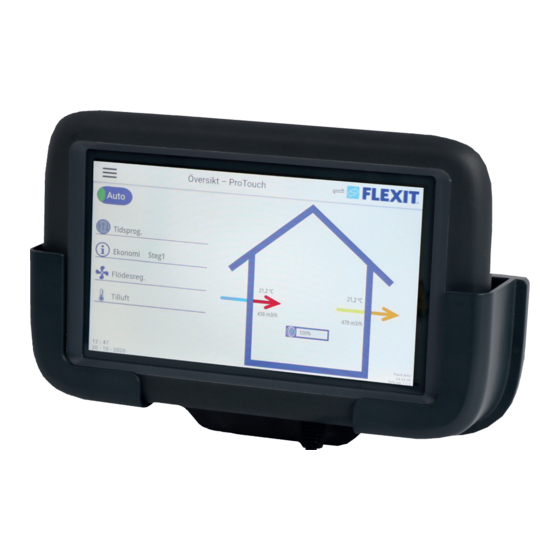
Page 7: Overview
Overview The Overview is the starting page on the panel, where you can see a simple overview of the most important parameters. The appearance of the overview image E.g. if heating and cooling coils or other accessories are activated, they will be shown in the overview. 3.1. -
Page 8: Main Menu
P R O T O U C H 3.2. Main menu Flow diagram of the unit Shows that the panel is communicating with the unit Overview diagram Alarm handling Information Menu for trends about the panel and software Login menu Time setting Panel settings calendar... -
Page 9: Flow Diagram
3.3. Flow diagram All values are in the current mode. 1. Link to main menu 2. Status of service cut-out-switch 13. Extract air temperature 4. Temperature mode 14. Rotating heat exchanger and force 5. Fan regulation type 15. Outdoor temperature 16. -
Page 10: Service Switch
P R O T O U C H Service switch The service switch is used to stop the unit for servicing. NB. If an electric heating coil is installed and active, there pressing X. will be 180 seconds run-on time to cool down the coil before the unit stops. -
Page 11: Alarm
Alarm Settings Under Settings on the main menu it is possible to make overview screen. To see and reset the alarm, go to the various adjustments in the panel. menu overview. 1. Press on the main menu. 2. Then press Alarm. •... -
Page 12: Trends
P R O T O U C H Trends Some values can be logged in the panel (e.g. temperature, to the right can be selected for logging. Press the arrow and hold it down until it changes colour to red to place it in the trend tool. 1. -
Page 13: Connection
Connection via the Cloud - Not used with Flexit products. If you are connected to the unit, two arrows will be shown to the left of the Flexit log. If the arrows are Check the cabling. Monday. temperature) of the time channel, press the... - Page 14 P R O T O U C H 4. To add a new time channel, press on the + sign and 7. When you have set Monday, you can copy the select the time when the time channel will start to settings to the other weekdays.
- Page 15 P R O T O U C H...
- Page 16 Flexit AS, Televeien 15, N-1870 Ørje www.flexit.no...
Need help?
Do you have a question about the ProTouch 118257 and is the answer not in the manual?
Questions and answers