
Related Manuals for GEA T.VIS A-15


Summary of Contents for GEA T.VIS A-15
- Page 1 Control and feedback systems ® GEA T.VIS A-15 Operating instruction (Translation from the original language) 430BAL010699EN_9...
-
Page 2: Test Procedure
EU Machinery Directive. This document is protected by copyright. All rights reserved. The document may not, in whole or in part, be copied, reproduced, translated or reduced to an electronic medium of machine-readable form without the express permission of GEA Tuchenhagen GmbH. LEGAL NOTICE Word marks ®... -
Page 3: Table Of Contents
TABLE OF CONTENTS General Information Information on the Document 1.1.1 Binding Character of These Operating Instructions 1.1.2 Notes on the Illustrations 1.1.3 Symbols and Highlighting Manufacturer address Contact EU Declaration of Conformity Translated copy of the EU Declaration of Conformity UK Declaration Translated copy of the UK Declaration of Conformity according to the provisions on electromagnetic compatibility from 2016... - Page 4 6.3.3 Control top with 2 solenoid valves – for lifting the double-disk, for the external air connection of an air/air actuator or for the main stroke of an external process valve 6.3.4 Control top with 2 solenoid valves- for spreader lift of the double-disk 6.3.5 Control top with 3 solenoid valves for lifting the valve disk and double-disk 6.3.6...
- Page 5 Spare parts list - control top type T.VIS A-15 Spare parts list - switch bar T.VIS A-15 Dimension sheet - Control top type T.VIS A-15 Dimension sheet - switch bar LFT-R T.VIS A-15/M-20 for lifted valves R; T_R; L; M_O(06); MT/T_R(08); M/2.0; MT; MT-DA; MX Appendix 17.1...
- Page 6 430BAL010699EN_9 11.01.2024...
-
Page 7: General Information
General Information Information on the Document General Information Information on the Document The present Operating Instructions are part of the user information for the product. The Operating Instructions contain all the information you need to transport, install, commission, operate and carry out maintenance for the product. 1.1.1 Binding Character of These Operating Instructions These Operating Instructions contain the manufacturer's instructions to the... -
Page 8: Manufacturer Address
Second step in a sequence of operations. ® Result of the previous operation. ® The operation is complete, the goal has been achieved. Hint! Further useful information. Manufacturer address GEA Tuchenhagen GmbH Am Industriepark 2-10 21514 Büchen Contact Tel.:+49 4155 49-0 Fax:+49 4155 49-2035 flowcomponents@gea.com www.gea.com 430BAL010699EN_9 11.01.2024... -
Page 9: Eu Declaration Of Conformity
General Information EU Declaration of Conformity EU Declaration of Conformity EU Declaration of Conformity Manufacturer: GEA Tuchenhagen GmbH Am Industriepark 2-10 21514 Büchen, Germany We hereby declare that the devices named below Control Top T.VIS ® A-15 Model: Control top T.VIS ®... -
Page 10: Translated Copy Of The Eu Declaration Of Conformity
General Information Translated copy of the EU Declaration of Conformity Translated copy of the EU Declaration of Conformity Manufacturer: GEA Tuchenhagen GmbH Am Industriepark 2-10 21514 Buchen, Germany We hereby declare that the devices named below Model: ® Control top T.VIS A-15 ®... -
Page 11: Declaration
General Information UK Declaration UK Declaration UK- Declaration of Conformity by Electromagnetic Compatibility Regulations 2016 Manufacturer: GEA Tuchenhagen GmbH Am Industriepark 2-10 21514 Büchen, Germany Hereby, we declare that the machine designated in the following Model: Control top T.VIS ®... -
Page 12: Translated Copy Of The Uk Declaration Of Conformity According To The Provisions On Electromagnetic Compatibility From 2016
Translated copy of the UK Declaration of Conformity according to the provisions on electromagnetic compatibility from 2016 Translated copy of the UK Declaration of Conformity according to the provisions on electromagnetic compatibility from 2016 Manufacturer: GEA Tuchenhagen GmbH Am Industriepark 2-10 21514 Büchen, Germany We hereby declare that the devices named below Model: ®... -
Page 13: Safety
For process valves which do not allow the air to be guided internally, the control top has a connection option for supplying the air externally via a hose. The control top T.VIS A-15 may not be used in areas where ATEX approval is required. Hint! -
Page 14: Subsequent Changes
EC Machinery Directive on your own. In general, only original spare parts supplied by GEA Tuchenhagen GmbH should be fitted. This ensures that the component is always operating properly and efficiently. -
Page 15: Ip Protection Classes
Safety IP Protection classes IP Protection classes The control top T.VIS A-15 in its standard version fulfils the requirements of protection class IP66, IP67 and IP69 (DIN EN 60529) and protection class IP6k9k (ISO 20653). IP classes provide information about the degree of protection an electrical device housing provides against the ingress of solids (first digit) or humidity (second digit). -
Page 16: Environmental Protection
Safety Supplementary Regulations The Operating Instructions must be kept ready to hand at the valve's place of • use. They must be complete and in clearly legible form. Only use the valve for its intended use. • The valve must be functional and in good working order. Check the condition •... -
Page 17: Qualification Of Personnel
Safety Qualification of personnel national regulations applicable in the country of use, • work and safety instructions applicable in the facility, • installation and operating regulations for use in potentially explosive areas. • Qualification of personnel This section provides information on how the personnel working on the component must be trained. -
Page 18: Safety Equipment
Safety Safety equipment User groups Staff Qualifications Operating personnel Adequate instruction and sound knowledge in the following areas: Functionality of the component • Operating sequences on the pump • What to do in case of an emergency • Lines of authority and responsibilities with respect to the task •... -
Page 19: Residual Dangers
Safety Residual dangers Signs on the control top Sign Meaning General hazard warning Fig.1 Warning Crushing Fig.2 Residual dangers Dangerous situations can be avoided by safety-conscious and proactive behaviour of the personnel and by wearing personal protective equipment. Residual dangers on the control top and measures Danger Cause Measure... - Page 20 Safety In the event of malfunctions, shut down the control top (disconnect from the • power and air supply) and secure it against being used. Before starting any service, maintenance or repair work, disconnect the • control top from the power supply and secure it against inadvertently being switched back on again.
-
Page 21: Description
3.1.2 Control top without solenoid valves The T.VIS A-15 control top without solenoid valves acts as a position indicator. After programming, it indicates the status of the process valve locally by coloured LEDs under the illuminated dome so that it is visible over a long distance. -
Page 22: Control Top With Cap Including Buttons
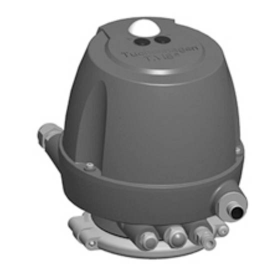
Fig.5: Control top with cap including buttons (standard variant in IP66) According to protection class IP66 (EN 60529) the control top T.VIS A-15 is suitable for use in this design and if the electrical and pneumatic connections are installed correctly. -
Page 23: Control Top With Hood Without Buttons
According to protection class IP66, IP67 and IP69 (DIN EN 60529) as well as protection class Ip6k9k (ISO 20653), the control top T.VIS A-15 is suitable for use in this design and if the electrical and pneumatic connections are installed correctly. -
Page 24: Safety Air Exhaust/Installation Position
Description 3.1.7 Safety Air Exhaust/Installation Position To provide protection against excess pressure which can build up in the inside of the control top, a vent plug E2 is fitted in the base. In operating mode, the exhaust air from the lifting actuators is discharged via this vent plug. In the unlikely event of a damaged solenoid valve or in case of sealing problems, pressure relief is ensured. -
Page 25: Transport And Storage
Transport and storage Storage conditions Transport and storage Storage conditions You must first dry and preserve the control top to prevent damage if the control top is exposed to temperatures ≤ 0°C during transport or storage. Hint! We recommend that the valve should be stored at a temperature of ≥ 5 °C for a period of 24 hours prior to any handling (disassembling the housings / activation of actuators) so that any ice crystals formed by condensation water can melt. -
Page 26: Technical Data
Item in the Designation Explanation order code Feedback location T A 1 5 Control top T.VIS A-15 Control top type without solenoid valve 1 solenoid valve 1 solenoid valve Y1 (retrofittable: Y2, Y3) 2 solenoid valves Y1= main stroke; Y4= spread lift double-disk 4 solenoid valves Y1 main stroke;... - Page 27 Technical data Type plate Explanation of the items in the order code Item in the Designation Explanation order code 3 solenoid valves 1 solenoid valve, 1 NOT element 2 solenoid valves, 1 NOT element 3 solenoid valves, 1 NOT element Feedback 3 digital feedbacks S1;...
- Page 28 Technical data Type plate Explanation of the items in the order code Item in the Designation Explanation order code 12-pin connector M12/9-wire/M20x1.5 24VDC (only for interface 24VDC and 4. feedback) 0.5 "NPT cable gland 24 V DC Options Supply air throttle: regulates the opening speed of the valves (cannot be used with control top type V;...
-
Page 29: Technical Data
Technical data Technical data Explanation of the items in the order code Item in the Designation Explanation order code /CD* UL 121201 - Non-incendive Electrical Equipment for Use in Class I, Division 2 , Hazardous (Classified) Locations. CSA C22.2 No. 213-17 - Non-incendive Electrical Equipment for Use in Class I, Division 2, Locations. - Page 30 Technical data Technical data Technical data: compressed air supply, product pressure and CIP pressure Designation Description 5 bar (72.5 psi) configuration with standard actuator max. 10 bar (116 psi) configuration Product pressure with correspondingly designed actuator > 10 bar (145.0 psi) for static applications and on request 2-5 bar (29-72.5 psi), a test may be CIP pressure...
-
Page 31: Specifications For 24V Dc Version
Technical data Specifications for 24V DC version * If cleaning agents are used that significantly reduce the surface tension and/or if high-pressure cleaners are used, we recommend using devices in optional protection class IP69 (DIN EN 60529) or Ip6k9k (ISO 20653). Specifications for 24V DC version Technical data: supply Designation... - Page 32 Technical data IO-Link specifications Technical data: supply Designation Description - One solenoid valve 35...45 mA Total approx. 135 mA Material number: 221-005030 --> from software version 0A (see version label 24V/0A) 221-005023 --> from software version A (see version label AIOL) Technical data: inputs as seen from the IO-Link Feedback Signal...
- Page 33 Technical data IO-Link specifications Technical data: inputs as seen from the IO-Link Feedback Signal 1= double-disk not spread Spread lift 0 = double-disk spread Double-disk (double-seated valves) 1 = valve in non- actuated position 0= valve disk and Main stroke double-disk not closed …...
- Page 34 Technical data IO-Link specifications Technical data: inputs as seen from the IO-Link Feedback Signal DIW X +2 Actual valve 0 … 1023 (10Bit) position Valve position 0 … 78mm * Assignment for colour variant green, see Section 6.5.2, Page 64. Technical data: outputs as seen from the IO-Link Actuation Signal...
- Page 35 Technical data IO-Link specifications Technical data: electrical specifications Designation Description V1.1 IO-Link version Port class A / COM2 Reverse voltage protection SIO mode not supported You can download the IODD from the following link: https://ioddfinder.io-link.com/productvariants/search?vendorName=%22GEA %20Tuchenhagen%20GmbH%22 Technical data: non-cyclical data exchange Sub- Access Offset...
-
Page 36: Specifications For As-Interface
Technical data Specifications for AS-interface Technical data: non-cyclical data exchange Sub- Access Offset Function Range Default Signal index rights 0x07 0x06 0x00 - 0x04 0 … 1023 (10Bit) Activated Position 0x08 0x07 0x00 - 0xFF 0 … 78mm 0x09 0x08 0x00 - 0x04 0 …... - Page 37 Technical data Specifications for AS-interface Technical data: inputs as seen from the AS-interface master Feedback Signal 0 = double-disk not Double-disk closed or no external sensor present not assigned * Assignment for colour variant green, see Section 6.5.2, Page 64. from software version C (see version label #ASI) Technical data: inputs as seen from the AS-interface master Feedback...
-
Page 38: Devicenet Specifications
Technical data DeviceNet specifications Technical data: inputs as seen from the AS-interface master Feedback Signal (double-seated valves) 1 = valve in non- actuated position 0= valve disk and Main stroke double-disk not closed Technical data: outputs as seen from the AS-interface master Actuation Signal 1 = solenoid valve... - Page 39 Technical data DeviceNet specifications Technical data: supply Designation Description Supply voltage UV 11...26 V DC without solenoid valve Supply voltage UV 21...26 V DC with solenoid valve Current consumption - No-load current ≤ 35 mA - One solenoid valve 35...45 mA Total approx.
- Page 40 Technical data DeviceNet specifications Technical data: outputs as seen from the DeviceNet master Actuation Signal 1 = solenoid valve activated PV Y3 Activation of solenoid valve 0 = solenoid valve not activated not assigned Software version C (see version label CDN) Technical data: inputs as seen from the DeviceNet master Feedback Signal...
- Page 41 Technical data DeviceNet specifications Technical data: outputs Actuation Signal 1 = solenoid valve PV Y1 activated Activation of solenoid valve 0 = solenoid valve not activated 1 = solenoid valve PV Y2 activated Activation of solenoid valve 0 = solenoid valve not activated 1 = solenoid valve PV Y3 (if PV Y1 = 0)
- Page 42 Technical data DeviceNet specifications Switches 1 and 2 = baud rate DIP 1 DIP 2 Baud rate 125 kBaud 250 kBaud 500 kBaud Selectable via software Delivery state Fig.11: DIP switches: switches 3 and 8 = MAC ID (address) Switches 3 to 8 = MAC ID (address) DIP 3 DIP 4 DIP 5...
-
Page 43: Accessories
Technical data Accessories Fig.12 Accessories Accessories must be ordered separately. Accessories Part no. Cable socket, right-angle – M12; 5-pole: A-coded 508-963 Cable socket, straight – M12; 8-pole: A-coded 508-061 Cable socket, straight – M12; with 1 m cable and ASI insulation 508-027 displacement terminal Cable socket, straight –... -
Page 44: Tool
Technical data Tool Tool List of tools Tool Material no. Hose cutter 407-065 Hex key, size 3 408-121 Pin-type face spanner, pin dia. 4 9065837 Open-ended wrench a/f 23 408-046 Open end spanner a/f 16x18 408-138 Open-ended wrench a/f 15 408-035 Open end spanner a/f 13x17 408-036... - Page 45 Technical data Technical data - equipment Equipment Material no. Sound absorber G 1/8" Filter material: stainless steel wool • 933-175 Ambient temperature: -20...+70 °C • max. pressure 10 bar • Sound absorber G 1/4" Filter material: stainless steel wool • 933-174 Ambient temperature: -20...+70 °C •...
-
Page 46: Assembly And Installation
Assembly and installation Safety instructions Assembly and installation Safety instructions Hazardous situations during installation can be avoided by safety-conscious and proactive behaviour of the personnel. For installation, the following principles apply: Only qualified personnel are allowed to set-up, install and commission the •... -
Page 47: Control Top With 1 Solenoid Valve Or Without Solenoid Valve
Before removing a sealing plug (23), make sure that the respective air connection is pressure-free! On most of the GEA Tuchenhagen valve types, solenoid valve Y1 internally guides the main control air through the switch bar into the main actuator. The external air connection Y1 is provided in addition. -
Page 48: Control Top With 2 Solenoid Valves - For Lifting The Valve Disk
Before removing a sealing plug (23), make sure that the respective air connection is pressure-free! On most of the GEA Tuchenhagen valve types, solenoid valve Y1 internally guides the main control air through the switch bar into the main actuator. The external air connection Y1 is provided in addition. -
Page 49: Control Top With 2 Solenoid Valves - For Lifting The Double-Disk, For The External Air Connection Of An Air/Air Actuator Or For The Main Stroke Of An External Process Valve
Before removing a sealing plug (23), make sure that the respective air connection is pressure-free! On most of the GEA Tuchenhagen valve types, solenoid valve Y1 internally guides the main control air through the switch bar into the main actuator. The external air connection Y1 is provided in addition. -
Page 50: Control Top With 2 Solenoid Valves- For Spreader Lift Of The Double-Disk
Before removing a sealing plug (23), make sure that the respective air connection is pressure-free! On most of the GEA Tuchenhagen valve types, solenoid valve Y1 internally guides the main control air through the switch bar into the main actuator. The external air connection Y1 is provided in addition. -
Page 51: Control Top With 3 Solenoid Valves For Lifting The Valve Disk And Double-Disk
Before removing a sealing plug (23), make sure that the respective air connection is pressure-free! On most of the GEA Tuchenhagen valve types, solenoid valve Y1 internally guides the main control air through the switch bar into the main actuator. The external air connection Y1 is provided in addition. - Page 52 Assembly and installation Pneumatic connections Hint! To ensure adequate compressed air supply to the process actuators, a max. of 2 solenoid valves are electrically activated at the same time! It must be ensured that there can be no simultaneous control of the actuator or the lifts at the same process valve! 430BAL010699EN_9 11.01.2024...
-
Page 53: Control Top With 3 Pilot Valves - To Lift The Double-Disk And To Spread Lift The Double-Disk
Before removing a sealing plug (23), make sure that the respective air connection is pressure-free! On most of the GEA Tuchenhagen valve types, solenoid valve Y1 internally guides the main control air through the switch bar into the main actuator. The external air connection Y1 is provided in addition. -
Page 54: Control Top With 4 Pilot Valves For The Lift Of The Valve Disk And Of The Double-Disk And For The Spread Lift Of The Double-Disk
Assembly and installation Pneumatic connections 6.3.7 Control top with 4 pilot valves for the lift of the valve disk and of the double-disk and for the spread lift of the double-disk Fig.19: Control top (standard variant in IP66) Exhaust air of the main stroke Y1 with sound absorber optional: exhaust air throttle Connection E1 must not be closed! Safety vent against excess pressure and exhaust air of lifting actuators... -
Page 55: Electrical Connections
Assembly and installation Electrical connections On most of the GEA Tuchenhagen valve types, solenoid valve Y1 internally guides the main control air through the switch bar into the main actuator. The external air connection Y1 is provided in addition. Hint! To ensure adequate compressed air supply to the process actuators, a max. -
Page 56: Overview
Assembly and installation Electrical connections 6.4.1 Overview 24.1 Fig.20 Fig.21 Danger Only allow properly qualified staff to carry out work on the electrical equipment. Prior to establishing electrical connections check the maximum permissible operating voltage. ► 430BAL010699EN_9 11.01.2024... -
Page 57: Electrical 24 V Dc Wiring
Assembly and installation Electrical connections Hint! The electrical cable must be long enough to allow the control top to be removed via the switch bar! The cables must be suitable for use in the temperature range from -20 °C to 75 °C! 6.4.2 Electrical 24 V DC Wiring 6.4.2.1 Plug M12 / 5-pin (24.1) -
Page 58: Connector M12 / 8-Pin (24.1)
Assembly and installation Electrical connections 6.4.2.2 Connector M12 / 8-pin (24.1) Fig.23: 8-pin M12 plug-in connector A-coded: device connector and view of pin strip Corresponding cable socket part no. 508-061. L+24V DC supply voltage Feedback end position valve L- reference potential Feedback non-actuated position valve Actuation of solenoid valve Y1 Actuation of solenoid valve Y2... -
Page 59: 6.4.2.3 Connector M12/12-Pin / 9-Strand
Assembly and installation Electrical connections 6.4.2.3 Connector M12/12-pin / 9-strand Fig.24: 12-pin M12 plug-in connector A-coded: device connector and view of pin strip L+24V DC supply voltage Feedback end position valve L- reference potential Feedback idle position valve disk closed Actuation of solenoid valve Y1 Actuation of solenoid valve Y2 Actuation of solenoid valve Y3... -
Page 60: Cable Gland
Assembly and installation Electrical connections 6.4.2.4 Cable gland (24) Fig.25: Terminal assignment of the optional additional board 24VDC (78), material no. 221-005025 Carry out the following steps: Insert the cable (diameter 6-12 mm) through the cable gland (24) and connect to the additional board (78) in the control top according to the connection diagram. -
Page 61: Electrical Wiring Of As-Interface
Assembly and installation Electrical connections Not connected IO-Link Not connected *For assignment for green colour variant, see Section 6.5, Page 63 Carry out the following steps: Connect cable via air connector M12/5-pin. ® Done. 6.4.4 Electrical Wiring of AS-Interface 6.4.4.1 Plug M12 / 5-pin (24.1) Fig.27: 5-pin M12 plug-in connector A-coded: device connector and view of pin strip Associated cable sockets part 508-027, 508-028 and 508-963. -
Page 62: Plug M12 / 5-Pin (24.1)
Assembly and installation Electrical connections 6.4.5.1 Plug M12 / 5-pin (24.1) Fig.28: 5-pin M12 plug-in connector A-coded: device connector and view of pin strip Corresponding cable sockets part no. 508-963. Not connected CAN_H CAN_L Carry out the following steps: Connect cable via air connector M12/5-pin. ®... -
Page 63: Visual Display
Assembly and installation Visual Display Insert the cable (Ø 3-7mm) through the cable gland (50) and connect it to the terminals (K1) and (K2) in the control top according to the connection diagram. Secure the cable in the cable gland at a tightening torque of 2.5 Nm. ®... -
Page 64: Colour Changeover
Assembly and installation Visual Display Control top not programmed: flashing 3 times - pause - flashing 3 times - pause Default, special version: • Control top not programmed: flashing 2 times - pause - flashing 2 times - pause There is a power failure if no signal is displayed for more than 5 seconds! 6.5.2 Colour Changeover The "colour changeover"... -
Page 65: Connection Diagram For T.vis Circuit Board (Bottom)
Assembly and installation Visual Display 6.5.3 Connection diagram for T.VIS circuit board (bottom) Fig.31 24VDC 221-005031 with spread lift 221-005026 Fig.32 430BAL010699EN_9 11.01.2024... - Page 66 Assembly and installation Visual Display 24VDC 221-005031 with IO-Link 221-005023 and spread lift 221-005026 Fig.33 Explanation of the pin assignment Plug position Connector type Item no. in the Designation Spare Parts List Plug-in connector M12/5- PicoBlade 5-pin 24.1 wire/M20 J1 IO-Link PicoBlade 5-pin Voltage supply PicoBlade 5-pin...
-
Page 67: Mounting The Control Top To Different Valves
Assembly and installation Mounting the control top to different valves Explanation of the pin assignment Plug position Connector type Item no. in the Designation Spare Parts List PicoBlade 2-pin Solenoid valve Y3 Cable connection external Terminal strip initiator Explanation of the pin assignment of spread lift printed circuit board mat. no. 221-005026 (fig. -
Page 68: Fitting To Flowvent Valve
Align the pneumatic and electrical connections in accordance with the valve block configuration. Close the air connection Y1 with a sealing plug (23) since the control top T.VIS A-15 has an inner air duct. Fig.35 Perform commissioning, see Chapter 6, Page 46 and Chapter 7, Page 80. - Page 69 Assembly and installation Mounting the control top to different valves Fig.36 Carry out the following steps: Insert the O-ring (F1) into the lower O-ring groove of the installation base (F). Lightly grease the O-ring (F1) and the inner thread of the installation base (F) and then screw the installation base onto the actuator and tighten using a pin- face spanner and a tightening torque of 20 Nm.
-
Page 70: Installation On Varivent Mixproof Valves With Lifting Actuator Type R, T_R, M/2.0, M_0(06), Mt/T_R
Tighten the half rings (15) and screws (39) to a tightening torque of 1 Nm (0.7 lbft). Align the pneumatic and electrical connections in accordance with the valve block configuration. Close the air connection Y1 with a sealing plug (23) since the control top T.VIS A-15 has an inner air duct. 430BAL010699EN_9 11.01.2024... -
Page 71: Mounting To A Butterfly Valve T-Smart 8000
Assembly and installation Mounting the control top to different valves Fig.38 Perform commissioning, see Chapter 6, Page 46 and Chapter 7, Page 80. ® Done. 6.6.4 Mounting to a Butterfly Valve T-smart 8000 Requirement: Pay attention not to kink the air hoses when mounting the control top. •... -
Page 72: Mounting To A Butterfly Valve T-Smart 7 And A Mixproof Butterfly Valve T-Smart 9
Align the pneumatic and electrical connections in accordance with the valve block configuration. Close the air connection Y1 with a sealing plug (23) since the control top T.VIS A-15 has an inner air duct. Fig.40 Perform commissioning, see Chapter 6, Page 46 and Chapter 7, Page 80. -
Page 73: Mounting To Ecovent Valves N_Eco And W_Eco
Mounting the control top to different valves Close the air connection Y1 with a sealing plug (23) since the control top T.VIS A-15 has an inner air duct. Fig.42 Perform commissioning, see Chapter 6, Page 46 and Chapter 7, Page 80. -
Page 74: Mounting To Vesta Valve H_A/M
Align the pneumatic and electrical connections in accordance with the valve block configuration. Due to the internal air guiding of the control top T.VIS A-15 (B), the connection A 4.2 on the actuator and air hose Y1 (23) on the steering top are closed. -
Page 75: Mounting To Vesta Valve H_A
Assembly and installation Mounting the control top to different valves Fig.45 Screw the mounting base (198) into the actuator (A4) and tighten using a face spanner. Screw switch bar (1) with ring (99) into the piston rod (A4.1) and tighten with jaw wrench SW 13, tightening torque 2 Nm (1.4 lbft). -
Page 76: Mounting To Valve N_/E Or W_/E Or Stericom Valve
Assembly and installation Mounting the control top to different valves Fig.46 Screw the adapter into the actuator (A4.1) and tighten using an a/f 17 open end spanner. Complete the T.VIS mounting base (198) with O-rings (29, 101) and a plain bearing (202). -
Page 77: Mounting To A T-Smart Single-Seat And Double-Seal Valve
Assembly and installation Mounting the control top to different valves Complete the T.VIS mounting base (198) with O-rings (29, 101) and a plain bearing (202). Fig.48 Fig.47 Screw the adapter T.VIS E/SHO (139) into the actuator with jaw wrench on wrench surface (139.1) and tighten. -
Page 78: Fitting To An Aseptomag Valve
Assembly and installation Mounting the control top to different valves Fig.49 Requirement: Pay attention not to kink the air hoses when mounting the control top. • Carry out the following steps: Screw the switch bar (1) into the piston rod A4.1 and tighten by applying an a/f 13 jaw wrench at (1.1), tightening torque 2 Nm. -
Page 79: Replacing Control Tops
If a valve with the wrong type of switch bar is used, there is a risk of injury as the switch bar can damage the pneumatic block. ► When replacing a predecessor model with a control top T.VIS A-15 the switch bar must always be replaced! 430BAL010699EN_9 11.01.2024... -
Page 80: Start-Up
Start-up Safety notes Start-up Safety notes Initial commissioning For initial commissioning, the following principles apply: Take protective measures against dangerous contact voltages in accordance • with pertinent regulations. The control top must be completely assembled and correctly adjusted. All • screw connections must be securely tightened. -
Page 81: Commissioning - Control Top With Solenoid Valves
Once the control top has been properly mounted on the valve and the electrical connections have been established correctly, commissioning can be carried out. Since the T.VIS A-15 detects its solenoid valve fitting and therefore requires corresponding process valve conditions, the so-called special default must selected prior to SETUP in the event of a different. - Page 82 Page 101. ® If 24/7 PMO valves (types M_O (06), M/2.0, MT/T_T (08) are used in conjunction with the control top T.VIS A-15, the factory settings in the control top may not be changed. ® If no selection is made within 30 seconds, the setting last selected is automatically adopted and visualized in accordance with the colours selected.
-
Page 83: Service Function
If maintenance must be conducted on a process valve that is fitted with a control top T.VIS A-15, the valve core must be pulled out of the housing. For this purpose, the valve disk pretension of the process valve must be relieved by actuating the main actuator. - Page 84 Start-up Adjust the initiator in the lantern - for unbalanced double-disks of the valves D, R, Y, B, T_R and MT Turn the nut NI (2) in the slot (4.1) in the lantern through 90° and tighten with the countersunk screw (3). Fig.55 Done.
- Page 85 Start-up Adjust the initiator in the lantern - for unbalanced double-disks of the valves D, R, Y, B, T_R and MT Fig.58 ® Done. Adjusting the proximity switch Carry out the following steps: Unscrew the proximity switch by one full turn (360°) to set the gap (a) in the range from 0.5 to 1.0 mm.
-
Page 86: Adjust The Initiator In The Lantern - For Double-Disk Of The Tank Bottom Valves Mt-Da (Spreader Lift)
Adjust the initiator in the lantern - for double-disk of the tank bottom valves MT-DA (spreader lift) Hint! Only in combination with T.VIS A-15. Fig.60: 1 = Initiator / 2 = Initiator The valve type MT DA contains tow initiators located in the lantern. Initiator 1 monitors the rest position of the double-disk resp. - Page 87 Start-up Adjust the initiator in the lantern - for unbalanced double-disks of the valves D, R, Y, B, T_R and MT The valve has to be in the non-actuated rest position for adjustment of initiator 1. To adjust initiator 2, please actuate the valve via the PLC to the main stroke position.
- Page 88 Start-up Adjust the initiator in the lantern - for unbalanced double-disks of the valves D, R, Y, B, T_R and MT Fig.62 Done ® Adjusting the proximity switch holder Carry out the following steps: Screw the adjusting mandrel (6) into the proximity switch holder until it reaches the upper edge of the leakage indicator (7).
- Page 89 Start-up Adjust the initiator in the lantern - for unbalanced double-disks of the valves D, R, Y, B, T_R and MT Fig.63 Position the proximity switch holder by slightly loosening the countersunk screw in the lantern recess in such a way that the tip of the adjusting mandrel (6) is resting on the collar of the leakage indicator (7) facing the drive (A), see Figure 63.
- Page 90 Start-up Adjust the initiator in the lantern - for unbalanced double-disks of the valves D, R, Y, B, T_R and MT Fig.64 430BAL010699EN_9 11.01.2024...
- Page 91 Start-up Adjust the initiator in the lantern - for unbalanced double-disks of the valves D, R, Y, B, T_R and MT Fig.65 ® Done Fitting the proximity switch Carry out the following steps: Remove the adjusting mandrel (6). Screw in the proximity switch M12 (8) together with the counter nut (11) into the proximity switch holder (12) up to the leakage indicator (7).
- Page 92 Start-up Adjust the initiator in the lantern - for unbalanced double-disks of the valves D, R, Y, B, T_R and MT Fig.66 ® Done Adjusting the proximity switch Carry out the following steps: Unscrew the proximity switch (8) by one full turn (360°) to set the gap (a) by 0.5 to 1.0 mm.
-
Page 93: Adjusting The Proximity Switch In The Lantern Of Pmo Valve Type M/2.0
Start-up Adjusting the Proximity Switch in the lantern of PMO Valve Type M/2.0 Fig.67: 1 = Initiator / 2 = Initiator Tighten the counter nut (11). Attach the connector (10), that is already connected electrically to the control panel, on the proximity switch using the cap nut M12 (10.1). The LED on the proximity switch must now be lit in operating mode. - Page 94 Start-up Adjusting the Proximity Switch in the lantern of PMO Valve Type M/2.0 Secure the sliding piece (1) with the countersunk screw (3). Pay attention that the orientation is as shown in the diagram. The mounting hole (1.1) must face in the direction of the housing (5).
-
Page 95: Test Procedure For Tuchenhagen Pmo Valves Type M
Start-up Test procedure for Tuchenhagen PMO valves type M / 2.0 Fitting the proximity switch Carry out the following steps: Remove the adjusting screw (6). 2. Screw the proximity switch M12 (8), together with the lock nut (11), into the holder as far as the balancer (7). -
Page 96: Purpose
7.7.3 Hardware Description Three solenoid valves are installed in the control top T.VIS A-15: Solenoid valve Y1 – actuation of main valve Solenoid valve Y2 – lifting of lower seat Solenoid valve Y3 – lifting of upper seat Solenoid valve Y4 - lifting of upper seat if main stroke is activated. - Page 97 Start-up Test procedure for Tuchenhagen PMO valves type M / 2.0 When the seat moves downwards (approx. 6 mm), the green LED on the ® top of the control top will turn off and changes to a yellow flashing light (LEFF deactivate) or a green/yellow flashing light (LEFF activated) to indicate that the position detection device is detecting that the lower valve disk has left the closed position.
- Page 98 Start-up If the upper housing is part of the active CIP circuit: Activate lifting of the lower seat by activating solenoid valve Y2 via the PLC. If the lower housing is part of the active CIP circuit: Activate lifting of the upper seat by activating solenoid valve Y3 via the PLC. ®...
-
Page 99: Operation And Control
If the tolerance is not set in accordance with the intended purpose, this can result in malfunctions of the valve. GEA Tuchenhagen will not accept any liability for damage resulting from improper setting: the risk lies entirely with the operator of the facility. - Page 100 This allows user-specific process sequences to be optimally set. For the reliable monitoring of the valve seat seal GEA Tuchenhagen recommends the factory setting without signal attenuation. GEA Tuchenhagen will not accept any liability for damage resulting from the use of signal attenuation.
-
Page 101: Operating Overview
Operation and control Operating Overview Operating Overview Initial situation: T.VIS A‐15 de‐energised! First commissioning (not programmed; Recommissioning (programmed; Service (push buttons automatically locked after SETUP) push buttons are locked 30s after power on) Dis‐/Assembling Störung detektiert Störung detektiert Mounting of valve insert Decision: Use according product code? Decision: New SETUP necessary? ‐ press for 3…7s press and hold Power up Power up Power up Betriebsspannung Ein Power up Betriebsspannung Ein Power up Activation of main stroke to eliminate spring force. Default standard Default special Attention! 3x red flashing/Pause 2x red flashing/Pause If power will be switched off the valve disk will return ‐... - Page 102 Operation and control Operating Overview First commissioning or recommissioning under process conditions! Initial situation: T.VIS A‐15 de‐enrgized! First commissioning (not programmed; Recommissioning (programmed; push buttons automatically locked after SETUP) push buttons are locked 30s after power on) Störung detektiert Störung detektiert Decision: Use according product code? Decission: New SETUP necessary? ‐ Press for 3…7s Power off Power up Power up Power up Betriebsspannung Ein ‐ Default standard Default special Press for 3…7s 3x red flashing/Pause 2x red flashing/Pause Programming mode Permanent red...
- Page 103 Operation and control Operating Overview Fig.76 430BAL010699EN_9 11.01.2024...
- Page 104 Operation and control Fig.77 430BAL010699EN_9 11.01.2024...
-
Page 105: Cleaning
Cleaning Cleaning Cleaning Cleaning Observe the safety data sheets supplied by the detergent manufacturers. Only use detergents which are not aggressive towards synthetic materials and the sealing materials used and which are non-abrasive. Hint! After all cleaning work, make sure that the control top still complies with all safety instructions in this operating manual and thus that intended use is still given. -
Page 106: Maintenance
Maintenance Safety instructions Maintenance 10.1 Safety instructions Maintenance and repair Before carrying out maintenance and repair work on the component's electrical equipment, perform the following steps in accordance with the "5 safety rules": Isolate from the power supply • Take appropriate measures to prevent switch on •... -
Page 107: Inspections
Maintenance Inspections Disconnect all power and utility lines. • Markings, e.g. on lines, must not be removed. • Do not climb on the component. Use suitable access aids and working • platforms. Mark the lines (if unmarked) prior to disassembly to ensure they are not •... -
Page 108: Maintenance Intervals
Maintenance Maintenance intervals 10.3 Maintenance intervals To ensure the highest operational reliability of the magnetic separator, all wearing parts should be replaced at longer intervals. The actual maintenance intervals can only be determined by the user since they depend on the operating conditions, for instance: daily period of use, •... -
Page 109: Dismantling The Control Top Into Its Components
Maintenance Dismantling the Control Top into its Components 10.5 Dismantling the Control Top into its Components 10.5.1 Variants of the Control Top The control top can be fitted with: 3 solenoid valves (63) and without or with 1 logic element NOT (64) or •... -
Page 110: Install The Circuit Board
Maintenance Dismantling the Control Top into its Components Fig.81 Hint! IO-Link version can be seen on the label. Remove all wires from the printed circuit board (43). Done ® Hint! In order to avoid or minimize the possibility of damage from electrostatic discharge: Observe the requirements of DIN EN 61340-5-1 and 5-2. -
Page 111: Removing The Logic Element Not (Seal Pack)
Maintenance Dismantling the Control Top into its Components Fig.82 Lift the sensor module (9) off the base plate. ® Done 10.5.6 Removing the logic element NOT (seal pack) Requirement: Logic element NOT is only provided in connection with the pneumatic block •... -
Page 112: Removing The Solenoid Valves And The Valve Plate
Maintenance Dismantling the Control Top into its Components ! Place the logic element NOT, with adapter plate and seal, on the pneumatic block (8) as shown in the illustration. ! When inserting and tightening the screws, be careful to use existing threads. Fig.84 ®... -
Page 113: Removing The Pneumatic Block
Maintenance Dismantling the Control Top into its Components Warning! Long switch-on time and high ambient temperature. Risk of burns from the solenoid valve ► Allow to cool before dismantling. Carry out the following steps: Disconnect the electrical connection from the solenoid valve to the Pico Blade on the circuit board (43). -
Page 114: 10.5.10 Fitting The Pneumatic Block
Maintenance Dismantling the Control Top into its Components Requirement: If only the O-rings (42) and (55) must be changed then the solenoid valves • (63)/control plate (65) and element NOT (64) can remain on the pneumatic block (8). Carry out the following steps: Undo the screws (57.1, 57.2). -
Page 115: Install Pneumatic Connections
Maintenance Install pneumatic connections Fig.88 Fig.89 Pneumatic block (8.2) for max. 1 solenoid valve / pneumatic block (8) for max. 3 solenoid valves Tighten the screw (57.2): Tightening torque: 1.5 Nm (1.0 lbft). For other parts to be installed (sensor, circuit board, solenoid valves, control plate, element NOT) see previous pages. -
Page 116: Maintenance
Maintenance Maintenance Designation Tightening torques Screw-in plug connection 2.0 Nm Sound absorber 2.0 Nm Locking screw 0.5 Nm Plug Sound absorber 2.0 Nm O-ring Carry out the following steps: Establish the pneumatic connections in accordance with the codes on the control top. -
Page 117: Mounting Cap
Maintenance Maintenance Fig.92 Requirement: Use only the throttle (21.1) and sound absorber (26) specified in the spare • parts list, see Chapter 13, Page 123. Carry out the following steps: Check the sound absorber (21, 26), non-return valve (26.1), filter (5.1) and exhaust air throttle (21.1) for free control air leakage and replace if necessary. - Page 118 Maintenance Fig.93 Carry out the following steps: Use three screws (25) to fasten the hood (7) on the base (5) to tightening torque 2 Nm. Done ® 430BAL010699EN_9 11.01.2024...
-
Page 119: Alarms
Alarms Malfunctions and remedies Alarms 11.1 Malfunctions and remedies In the event of malfunctions, immediately deactivate the valve and secure it against inadvertent reactivation. Malfunctions may only be remedied by qualified staff, who must observe the safety precautions. Malfunction, signalling, cause, remedy Malfunction Signalling Cause... - Page 120 Correct the lifting when lifting the valve stroke disk has not been reached. No feedback signal is Red LED flashing T.VIS A-15 in factory Programming pending at the PLC setting and not yet according to although one of the programmed...
-
Page 121: Carrying Out A Reset - Back To Default Standard
Carrying out a Reset – Back to Default Standard Malfunction, signalling, cause, remedy Malfunction Signalling Cause Remedy Red LED permanently T.VIS A-15 currently in Wait until programming mode programming mode ends Red LED flashing T.VIS A-15 has a Check the bellows and... -
Page 122: Decommissioning
Decommissioning Safety instructions Decommissioning 12.1 Safety instructions For shutting down, the following principles apply: Switch off the compressed air. • Switch off the component with the main switch. • Padlock the main switch (if fitted) in the off position to prevent it from being •... - Page 123 Spare parts list - control top type T.VIS A-15 Spare parts list - control top type T.VIS A-15 Fig.94 430BAL010699EN_9 11.01.2024...
- Page 124 TA18G...M TA18V...M TA18P...M TA18J...M TA18F...M TA18X...M Item Designation Material TA18L...M TA18M...M TA18Y...M For switch bar T.VIS A-15 refer to the separate spare parts list 221ELI010728EN. Base T.VIS-T18 PA12/L 221-646.100 221-646.100 221-646.100 221-646.100 Filter 221-003869 221-003.869 221-003.869 221-003869 Screw-in plug connection D 6.0...
- Page 125 933-949 - Thread-forming screw (only for IO-Link) 514-768 514-768 514-768 514-768 - Round plug-in connector M12/3 wire 508-039 508-039 508-039 508-039 Adapter 4PV 221-589.111 # Placeholder for version status (Please contact GEA Tuchenhagen if there are any questions.) 430BAL010699EN_9 11.01.2024...
-
Page 126: Spare Parts List - Control Top Type T.vis
TA18G...Z TA18V...Z TA18P...Z TA18J...Z TA18F...Z TA18X...Z Item Designation Material TA18L...Z TA18M...Z TA18Y...Z For switch bar T.VIS A-15 refer to the separate spare parts list 221ELI010728EN. Base T.VIS-T18 PA12/L 221-646.100 221-646.100 221-646.100 221-646.100 Filter 221-003869 221-003.869 221-003.869 221-003869 Screw-in plug connection D 6.35... - Page 127 933-949 - Thread-forming screw (only for IO-Link) 514-768 514-768 514-768 514-768 - Round plug-in connector M12/3 wire 508-039 508-039 508-039 508-039 Adapter 4PV 221-589.111 # Placeholder for version status (Please contact GEA Tuchenhagen if there are any questions.) 430BAL010699EN_9 11.01.2024...
- Page 128 TA18G...ZM TA18V...ZM TA18P...ZM TA18J...ZM TA18F...ZM TA18X...ZM Item Designation Material TA18L...ZM TA18M...ZM TA18Y...ZM For switch bar T.VIS A-15 refer to the separate spare parts list 221ELI010728EN. Base T.VIS-T18 PA12/L 221-646.100 221-646.100 221-646.100 221-646.100 Filter 221-003869 221-003.869 221-003.869 221-003869 Screw-in plug connection D 6.35...
- Page 129 933-949 - Thread-forming screw (only for IO-Link) 514-768 514-768 514-768 514-768 - Round plug-in connector M12/3 wire 508-039 508-039 508-039 508-039 Adapter 4PV 221-589.111 # Placeholder for version status (Please contact GEA Tuchenhagen if there are any questions.) 430BAL010699EN_9 11.01.2024...
- Page 130 Spare parts list - control top type T.VIS A-15 Item Designation Material Material no. 21.1 Throttle valve G 1/8 Brass/ 603-042 to reduce the closing speed main stroke (air outlet with nickel- sound absorber pos. 21) plated 21.2 Throttle valve G 1/8...
-
Page 131: Spare Parts List - Switch Bar T.vis
Spare parts list - switch bar T.VIS A-15 Spare parts list - switch bar T.VIS A-15 Fig.95 430BAL010699EN_9 11.01.2024... - Page 132 Spare parts list - switch bar T.VIS A-15 Item Designation Material Material no. Application Switch bar PA6/GK30 221-589.104 Standard for all valves with the exception of butterfly valves T- smart 7 and valves with lifting actuator R; T_R; L; M_O(06);...
-
Page 133: Dimension Sheet - Control Top Type T.vis
Dimension sheet - Control top type T.VIS A-15 Dimension sheet - Control top type T.VIS A-15 Fig.96 For assignment of N, Y1, Y2, Y3, E1, E2 and P refer to the Operating Instructions “Control Top T.VIS A-15”. X - supply voltage, electric actuation and feedback... -
Page 134: Dimension Sheet - Switch Bar Lft-R T.vis A-15/M-20 For Lifted Valves R; T_R; L; M_O(06); Mt/T_R(08); M/2.0; Mt; Mt-Da; Mx
Dimension sheet - switch bar LFT-R T.VIS A-15/M-20 for lifted valves R; T_R; L; M_O(06); MT/T_R(08); M/2.0; MT; MT-DA; MX Dimension sheet - switch bar LFT-R T.VIS A-15/M-20 for lifted valves R; T_R; L; M_O(06); MT/T_R(08); M/2.0; MT; MT-DA; MX Fig.97... - Page 135 Dimension sheet - switch bar LFT-R T.VIS A-15/M-20 for lifted valves R; T_R; L; M_O(06); MT/T_R(08); M/2.0; MT; MT-DA; MX Actuator Switch bar T.VIS A-15 Type Material no. Actuator Material no. Length 221-118.01 221-120.01 221-618.20 221-118.02 221-618.20 221-119.02 221-618.20 221-618.21 in valve DN25;...
- Page 136 Dimension sheet - switch bar LFT-R T.VIS A-15/M-20 for lifted valves R; T_R; L; M_O(06); MT/T_R(08); M/2.0; MT; MT-DA; MX Actuator Switch bar T.VIS A-15 Type Material no. Actuator Material no. Length SN6Z 221-585.05 260.5 221-618.24 EF6Z 221-585.07 221-618.24 EG6Z 221-585.08...
-
Page 137: Appendix
Appendix Lists Appendix 17.1 Lists 17.1.1 Abbreviations and terms Abbreviation Explanation British Standard Unit of measurement of pressure [bar] All pressure data expressed in [bar/psi] is assumed to be gauge pressure [barg/psig] unless explicitly specified otherwise. approx. approximately °C Unit of measurement of temperature [degree Celsius] Unit of measurement of volume [cubic decimetre] Standard volume (standard litre) DIN nominal width... - Page 138 Appendix Abbreviation Explanation Metric Unit of measurement of work [newton metre] Specification of torque 1 Nm = 0.737 lbft Pound-Force (lb) + Feet (ft) Polyamide PE-LD Low-density polyethylene Polytetrafluoroethylene America measurement for pressure [Pound-forse per square inch] All pressure data expressed in [bar/psi] is assumed to be gauge pressure [barg/psig] unless explicitly specified otherwise.
- Page 139 Appendix 430BAL010699EN_9 11.01.2024...
Need help?
Do you have a question about the T.VIS A-15 and is the answer not in the manual?
Questions and answers