
Related Manuals for GEA T.VIS M-20 FDD


Summary of Contents for GEA T.VIS M-20 FDD
- Page 1 Control and feedback systems ® GEA T.VIS M-20 FDD Operating instruction (Translation from the original language) 430BAL014475EN_2...
- Page 2 EU Machinery Directive. This document is protected by copyright. All rights reserved. The document may not, in whole or in part, be copied, reproduced, translated or reduced to an electronic medium of machine-readable form without the express permission of GEA Tuchenhagen GmbH. LEGAL NOTICE Word marks ®...
-
Page 3: Table Of Contents
TABLE OF CONTENTS General Information Information on the Document 1.1.1 Binding Character of These Operating Instructions 1.1.2 Notes on the Illustrations 1.1.3 Symbols and Highlighting Manufacturer address Contact EU Declaration of Conformity Translated copy of the EU Declaration of Conformity Safety Intended use 2.1.1... - Page 4 Maintenance 10.7.1 Replacing the Seals on the Base Alarms 11.1 Malfunctions and remedies Decommissioning 12.1 Safety precautions 12.2 Disposal 12.2.1 General notes Spare parts list - control top T.VIS M-20 FDD Appendix 14.1 Lists 14.1.1 Abbreviations and terms 430BAL014475EN_2 03.09.2021...
-
Page 5: General Information
General Information Information on the Document General Information Information on the Document The present Operating Instructions are part of the user information for the product. The Operating Instructions contain all the information you need to transport, install, commission, operate and carry out maintenance for the product. 1.1.1 Binding Character of These Operating Instructions These Operating Instructions contain the manufacturer's instructions to the... -
Page 6: Manufacturer Address
Second step in a sequence of operations. ® Result of the previous operation. ® The operation is complete, the goal has been achieved. Hint! Further useful information. Manufacturer address GEA Tuchenhagen GmbH Am Industriepark 2-10 21514 Büchen Contact Tel.:+49 4155 49-0 Fax:+49 4155 49-2035 flowcomponents@gea.com www.gea.com 430BAL014475EN_2 03.09.2021... -
Page 7: Eu Declaration Of Conformity
General Information EU Declaration of Conformity EU Declaration of Conformity EU Declaration of Conformity Manufacturer: GEA Tuchenhagen GmbH Am Industriepark 2-10 21514 Büchen, Germany We hereby declare that the devices named below Control Top T.VIS M-20 Model: 24 VDC Type:... -
Page 8: Translated Copy Of The Eu Declaration Of Conformity
General Information Translated copy of the EU Declaration of Conformity Translated copy of the EU Declaration of Conformity Manufacturer: GEA Tuchenhagen GmbH Am Industriepark 2-10 21514 Buchen, Germany We hereby declare that the devices named below Model: Control top T.VIS M-20... -
Page 9: Safety
The control top T.VIS M-20 FDD may not be used in areas where an explosion protection approval is required (e.g. ATEX, IECEx, CCCEx, HazLoc and other). -
Page 10: Operator's Duty Of Care
Safety Operator’s Duty of Care • Damage to the component has been detected. • Maintenance intervals have been exceeded. Operator’s Duty of Care The operating company of the component has a special responsibility for the proper and safe handling of the component within their company. Only use the component when it is in perfect operating condition in order to prevent danger to persons and property. -
Page 11: Ip Protection Classes
This ensures that the component is always operating properly and efficiently. IP Protection classes The control top T.VIS M-20 FDD in its standard version fulfils the requirements of protection class IP66, IP 67 and IP69 (DIN EN 60529) and protection class IP6k9k (ISO 20653). -
Page 12: Principles For Safe Operation
Safety General safety instructions and dangers 2.5.1 Principles for safe operation Dangerous situations during operation can be avoided by safety-conscious and proactive behaviour of the staff. To ensure safe operation of the valve the following principles apply: • The Operating Instructions must be kept ready to hand at the valve's place of use. -
Page 13: Supplementary Regulations
Safety Supplementary Regulations Supplementary Regulations In addition to the instructions in this documentation the following also has to be observed: • pertinent accident prevention regulations, • generally accepted safety rules, • national regulations applicable in the country of use, • work and safety instructions applicable in the facility, •... -
Page 14: Safety Equipment
Safety Safety equipment User groups Staff Qualifications Operating personnel Adequate instruction and sound knowledge in the following areas: • Functionality of the component • Operating sequences on the pump • What to do in case of an emergency • Lines of authority and responsibilities with respect to the task Maintenance personnel Appropriate training and a sound knowledge of the structure and functionality of the component. -
Page 15: Residual Dangers
• be careful not to touch the electronic components, • also take care not to touch electronic components when supply voltage is present. Use ESD-compliant packaging when returning electronic components. (Contact GEA Tuchenhagen if you have any questions.) 430BAL014475EN_2 03.09.2021... -
Page 16: Danger Zones
Safety Danger zones 2.10 Danger zones Please observe the following notes: • In the event of malfunctions, shut down the control top (disconnect from the power and air supply) and secure it against being used. • Before starting any service, maintenance or repair work, disconnect the control top from the power supply and secure it against inadvertently being switched back on again. -
Page 17: Description
Terminal strip unit Clamp connection Solenoid valves Cable gland Status light-emitting diode The control top T.VIS M-20 FDD consists of: • a 24 V DC sensor module for the detection of the two valve actuated positions, • a terminal strip unit for the switch-on type 24 V DC, •... - Page 18 Description Design Sensor module structure Printed circuit board switch-on type 24 VDC Fig.4 DIP switch Electronics Measuring track PV Y3 PV Y2 PV Y1 Reset 430BAL014475EN_2 03.09.2021...
-
Page 19: Functional Description
Functional description 3.2.1 Operation Principle The control top T.VIS M-20 FDD works with a microprocessor that contains the software for operation, visualization and intelligent position detection. The valve stroke is detected by a contactless position measuring system integrated in the control top and the information is supplied to the microprocessor. -
Page 20: Control Top With Cap
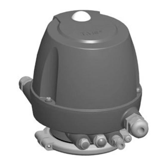
3.2.4 Control Top with Cap Fig.6: Control Top with Cap The control top T.VIS M-20 FDD in its standard version fulfils the requirements of protection class IP66, IP67 and IP69 (DIN EN 60529) and protection class IP6k9k (ISO 20653). 3.2.5... -
Page 21: Reset Function
Description This vent plug is a safety device that must be handled as such. Do not cover the vent plug. When fitting the control top note that the installation position of the vent plug (E2) must never be pointing vertically upwards. 3.2.6 Reset function In order to change saved positions (e.g. -
Page 22: Transport And Storage
Transport and storage Storage conditions Transport and storage Storage conditions You must first dry and preserve the control top to prevent damage if the control top is exposed to temperatures ≤ 0°C during transport or storage. Hint! We recommend that the valve should be stored at a temperature of ≥ 5 °C for a period of 24 hours prior to any handling (disassembling the housings / activation of actuators) so that any ice crystals formed by condensation water can melt. -
Page 23: Technical Data
Technical data Type plate Technical data Type plate The type plate is used to uniquely identify the control top. Fig.8: Type plate on control top (optional:UL/CSA marking) Code/Type TM20 Item in the order code Explanation of the items in the order code Item in the order code Designation Explanation... -
Page 24: Technical Data
Technical data Technical data Explanation of the items in the order code Item in the order code Designation Explanation Adhesive plate (valve no.) Certification UL/CSA For indoor use Technical data Refer to the following tables for the key technical data of the control top: Technical data: temperatures and compressed air supply Designation Description... -
Page 25: Specification Sensor Module 24V Dc Version
Technical data Specification sensor module 24V DC Version Technical data: electrical specifications Designation Description Protection class ISO 20653 IP69k - high pressure Fitting position Restriction through ventilation E2: Never direct ventilation (E2) vertically upwards EC EMC directives 2014/30/EU Immunity for industrial environments EN 61000-6-2: 2005 Radio frequency interference EN ISO 61000-6-4:2007 + A1: 2011... -
Page 26: Switching Point Tolerances And Signal Output
Technical data Switching point tolerances and signal output Switching point tolerances and signal output 5.4.1 Signal output Hint! Only use preset DIP switch configuration. Further positions lead to non-intended use. Main stroke - signal output Pilot valve actuation Valve position DIP switch Illumination Feedback... -
Page 27: Equipment
Technical data Equipment Equipment Technical data - equipment Equipment Material no. Solenoid valve NC • 24 V DC (+20% / -12.5%), 0.85 W • Ambient temperature: -20...+60°C 512-169 • Protection class IP 51 • Pressure range: 2.0...8.0 bar Sound absorber G 1/8" •... -
Page 28: Assembly And Installation
Assembly and installation Safety instructions Assembly and installation Safety instructions Hazardous situations during installation can be avoided by safety-conscious and proactive behaviour of the personnel. For installation, the following principles apply: • Only qualified personnel are allowed to set-up, install and commission the component. -
Page 29: Control Top With 1 Solenoid Valve Or Without Solenoid Valve
Assembly and installation Electrical connections 6.3.1 Control Top with 1 Solenoid Valve or Without Solenoid Valve Fig.9 Exhaust air of the main stroke Y1 (sound absorber) Connection E1 must not be closed! Safety vent against excess pressure Connection E2 must not be closed! Central air supply with integrated filter not used Air connection for external main stroke connection... -
Page 30: Electrical 24V Dc Wiring
Assembly and installation Electrical connections 6.4.1 Electrical 24V DC Wiring Fig.10 Danger Only allow properly qualified staff to carry out work on the electrical equipment. Prior to establishing electrical connections check the maximum permissible operating voltage. ► Carry out the following steps: Release the cheese head screws (25) and take off the cap (7). -
Page 31: Visual Display
Assembly and installation Visual Display 24V DC Cable Gland Fig.11: Terminal assignment of terminal strip unit 24V DC (78), material no. 221-589.108 Visual Display 6.5.1 Illuminated dome Fig.12 Position Description Illuminated dome The following statuses are visualized by the illuminated dome: 430BAL014475EN_2 03.09.2021... -
Page 32: Colour Changeover
Assembly and installation Control Top Fitted to VARIVENT Valve FDD • LED green, steady light: non-actuated position of the non-actuated process valve reached. • LED green, steady light with yellow flashing light: non-actuated position saved or actuated position not yet reached after main stroke (green 750ms/ yellow 250ms). -
Page 33: Replacing Control Tops
When a valve is used with the wrong type of switch bar, there is a risk of injury as the spring tension can suddenly be released. ► When replacing a predecessor model (only T.VIS M-15 FDD) with a control top T.VIS M-20 FDD the switch bar must always be replaced! 430BAL014475EN_2 03.09.2021... -
Page 34: Start-Up
Start-up Safety precautions Start-up Safety precautions Initial commissioning For initial commissioning, the following principles apply: • Take protective measures against dangerous contact voltages in accordance with pertinent regulations. • The control top must be completely assembled and correctly adjusted. All screw connections must be securely tightened. -
Page 35: Commissioning - Control Top With Solenoid Valve
Start-up Commissioning - Control Top with Solenoid Valve If necessary, activate the external solenoid valve until the process valve has reliably reached its actuated end position. Learning is completed when actuated and non-actuated position have been detected and learnt. If voltage is only switched off with one learnt position, the position already learnt is discarded. - Page 36 Start-up Commissioning - Control Top with Solenoid Valve Fig.13 Switch on the power supply. Activate automatic programming mode (keep reset key pressed for 3 - 7 sec.), see . The learning process starts automatically 1 - 2 seconds after reset. ®...
-
Page 37: Service Function
If maintenance must be conducted on a process valve that is fitted with a control top T.VIS M-20 FDD, the valve core must be pulled out of the housing. For this purpose, the valve disk pretension of the process valve must be relieved by actuating the main actuator. -
Page 38: Operation And Control
Operation and control Safety instructions Operation and control Safety instructions Dangerous situations during operation can be avoided by safety-conscious and proactive behaviour of the personnel. For operation, the following principles apply: • Monitor the component during operation. • Safety devices must not be changed, removed or taken out of service. Check all safety devices at regular intervals. -
Page 39: Cleaning
Cleaning Cleaning Cleaning Cleaning Observe the safety data sheets supplied by the detergent manufacturers. Only use detergents which are not aggressive towards synthetic materials and the sealing materials used and which are non-abrasive. Hint! After all cleaning work, make sure that the control top still complies with all safety instructions in this operating manual and thus that intended use is still given. -
Page 40: Maintenance
Maintenance Safety precautions Maintenance 10.1 Safety precautions Maintenance and repair Before carrying out maintenance and repair work on the component's electrical equipment, perform the following steps in accordance with the "5 safety rules": • Isolate from the power supply • Take appropriate measures to prevent switch on •... -
Page 41: Inspections
Maintenance Inspections • Disconnect all power and utility lines. • Markings, e.g. on lines, must not be removed. • Do not climb on the component. Use suitable access aids and working platforms. • Mark the lines (if unmarked) prior to disassembly to ensure they are not confused when re-assembling. -
Page 42: Maintenance Intervals
Maintenance Maintenance intervals 10.3 Maintenance intervals To ensure the highest operational reliability, all wearing parts should be replaced at longer intervals. The actual maintenance intervals can only be determined by the user since they depend on the operating conditions, for instance: •... -
Page 43: Removing The Control Top From The Valve
Maintenance Removing the Control Top from the Valve List of tools Tool Material no. Flat-nose pliers Pin punch/mandrel Ø6.0 mm 10.5 Removing the Control Top from the Valve Fig.15 Requirement: • Make sure that the solenoid valve is not actuated. Hint! The pneumatic and electrical connections can remain on the control top. -
Page 44: Removing The Solenoid Valve Or The Valve Plate
Maintenance Dismantling the Control Top into its Components Fig.16 Danger Electrical voltage Danger to life ► Switch off the voltage supply and the control air before removing the control top. Carry out the following steps: Undo the 3 screws (25) of the cap (7) and remove the cap (7) from the base (5). - Page 45 Maintenance Dismantling the Control Top into its Components Fig.17 Requirement: • Only use solenoid valves specified in chapter “Technical data”. Hint! In order to avoid or minimize the possibility of damage from electrostatic discharge: - Observe the requirements of DIN EN 61340-2-1 and 5-2. - Be careful not to touch the electronic components! Caution! Risk of burns from the solenoid valve as a result of long switch-...
-
Page 46: Removing The Sensor Module
Maintenance Dismantling the Control Top into its Components Fig.18 Pneumatic block (8.2) for max. 1 solenoid valve Hint! When using the pneumatic block (8.2) with one valve plate (65), the groove (65.12) must be fitted on the left side. The two screws (66) are located in the left mounting holes. -
Page 47: Removing The Pneumatic Block
Maintenance Dismantling the Control Top into its Components Grip the sensor module (43) by the mountain bracket and take out of the base (5). Ensure ESD-compliant handling. ® Done Hint! Fit the sensor module in the reverse order. Observe the wiring diagrams, see Page 18 10.6.5 Removing the pneumatic block... -
Page 48: Install Pneumatic Connections
Maintenance Dismantling the Control Top into its Components • Insert the journal (8.1) on the pneumatic block into the groove of the base (5)! Fig.21 Pneumatic block (8.2) for max. 1 solenoid valve Carry out the following steps: Fit the pneumatic block in the reverse order. ! Pneumatic block (8.2): First tighten screw (57.1), then screws (57.2): tightening torque 1.5 Nm (1.0 lbft). -
Page 49: Mounting Hood
Maintenance Maintenance Designation Tightening torques Locking screw 0.5 Nm Sound absorber 2.0 Nm O-ring Carry out the following steps: Establish the pneumatic connections in accordance with the codes on the control top. ® Done 10.6.8 Mounting hood Fig.23 Carry out the following steps: Use three screws (25) to fasten the hood (7) on the base (5) to tightening torque 1 Nm. - Page 50 Maintenance Only use sound absorber (21, 26) specified in chapter “Technical data” . Do not grease these spare parts before fitting them. Fig.24 Caution! ► On VARIVENT actuators with a vent hole in the actuator cover the control top may only be fitted without O-ring (54)! Carry out the following steps: Take out the O-rings (31, 53, 54) and replace them with new ones.
-
Page 51: Alarms
Alarms Malfunctions and remedies Alarms 11.1 Malfunctions and remedies In the event of malfunctions immediately deactivate the valve and secure it against inadvertent reactivation. Malfunctions may only be remedied by qualified staff, who must observe the safety precautions. Malfunction, signalling, cause, remedy Malfunction Signalling Cause... -
Page 52: Decommissioning
Decommissioning Safety precautions Decommissioning 12.1 Safety precautions For shutting down, the following principles apply: • Switch off the compressed air. • Switch off the component with the main switch. • Padlock the main switch (if fitted) in the off position to prevent it from being switched back on. -
Page 53: Spare Parts List - Control Top T.vis M-20 Fdd
Spare parts list - control top T.VIS M-20 FDD Spare parts list - control top T.VIS M-20 FDD Fig.25: (Ø 3.5 mm drilled hole for seal) 430BAL014475EN_2 03.09.2021... - Page 54 Spare parts list - control top T.VIS M-20 FDD Item Designation Material 24V DC with 1 solenoid without solenoid valve valve FDD-P FDD-N Control top T.VIS M-20 FDD cpl. 221-664.85 221-664.86 For switch bar T.VIS A-15/M-20 refer to the separate spare parts list 221ELI010728DE Base T.VIS-T18...
-
Page 55: Appendix
Appendix Lists Appendix 14.1 Lists 14.1.1 Abbreviations and terms Abbreviation Explanation British Standard Unit of measurement of pressure [bar] All pressure data expressed in [bar/psi] is assumed to be gauge pressure [barg/psig] unless explicitly specified otherwise. approx. approximately °C Unit of measurement of temperature [degree Celsius] Unit of measurement of volume [cubic decimetre] Standard volume (standard litre) DIN nominal width... - Page 56 Appendix Abbreviation Explanation Metric Unit of measurement of work [newton metre] Specification of torque 1 Nm = 0.737 lbft Pound-Force (lb) + Feet (ft) Polyamide PE-LD Low-density polyethylene Polytetrafluoroethylene America measurement for pressure [Pound-forse per square inch] All pressure data expressed in [bar/psi] is assumed to be gauge pressure [barg/psig] unless explicitly specified otherwise.
- Page 57 Appendix 430BAL014475EN_2 03.09.2021...
Need help?
Do you have a question about the T.VIS M-20 FDD and is the answer not in the manual?
Questions and answers