Advertisement
Quick Links
Advertisement

Related Manuals for Dufour Yachts Grand Large 455


Summary of Contents for Dufour Yachts Grand Large 455
- Page 1 OWNER’S MANUAL EN G LI S H 2 2 . 0 4 . 2 0 0 5...
- Page 2 French language. Dated: Signature: Detach along dotted line ………………………………………………………………………………………………………………… Owner's Manual receipt acknowledgement to be returned to DUFOUR YACHTS 1, Rue Blaise Pascal- 17187 PERIGNY CEDEX - FRANCE I, the undersigned: Name Address owner of DUFOUR 455 no.
-
Page 3: Table Of Contents
CONTENTS INTRODUCTION___________________________________________________________________________ 5 GENERAL INFORMATION ______________________________________________________________ 6 Design category ____________________________________________________________________ 6 Certification _______________________________________________________________________ 6 Identification ______________________________________________________________________ 6 Builder's plate _____________________________________________________________________ 7 MAIN SPECIFICATIONS______________________________________________________________ 8 III. ELECTRICAL SYSTEMS ______________________________________________________________ 9 Safety and operating instructions for the electrical system _________________________________ 9 Installing new equipment ____________________________________________________________ 9 Batteries _________________________________________________________________________ 10 Electric winch _____________________________________________________________________ 10 220/110 Volts Installation ___________________________________________________________ 11... - Page 4 Presentation plan ______________________________________________________________________ 28 Accommodation layout’ _______________________________________________________________ 29 III. Deck fittings plan ____________________________________________________________________ 30 Sail plan____________________________________________________________________________ 32 Halyard and sheet rigging plan _________________________________________________________ 34 110V Circuit diagram _________________________________________________________________ 36 VII. 220V Circuit diagram _________________________________________________________________ 38 VIII. Charging and power circuit diagram ___________________________________________________ 40 12 V / 220 V Electrical panel diagram ____________________________________________________ 42 Electrical panel terminal diagram _______________________________________________________ 44 12 V Electrical installation drawing______________________________________________________ 46...
-
Page 5: Introduction
DUFOUR YACHTS is delighted to present you with this manual that will enable you to get to know your boat better. This manual has been produced to help you enjoy the use of your boat in complete safety. It contains details about on board fittings and installations as well as information for use and maintenance. -
Page 6: General Information
So always take care before putting to sea. DUFOUR YACHTS is not able to guarantee perfect functioning of the boat in exceptional sea conditions (violent storms, hurricanes, cyclones, waterspouts,...) SUMMARY OF DESIGN CATEGORIES... -
Page 7: Identification
Builder identification plate is located in the cockpit. It contains important information that is explained below. Design category of yacht = A : Ocean-going (refer to 1.1) : Recommended by the builder for navigation in sea Maximum number of people = 10 conditions for category for which it was built. -
Page 8: Main Specifications
Model: DUFOUR 455 Designer: Umberto Felci Design category Notified organization no. CE/0607 LOA: 13·75 m Hull length: 13·45 m LWL: 11·91 m Maximum beam: 4·30 m Draught: 2·00 m Mast height clearance: 17·90 m Ballast weight: 3,000 kg Light displacement: ( safety) : (incl. safety 10,426 kg equipment): Displacement at maximum loading:... -
Page 9: Electrical Systems
WARNING Always: - Check the condition of the batteries (charge and electrolyte level) and the charging system before putting to sea. - Disconnect and remove batteries for wintering. - Do not let battery voltage drop below 10·5 V during wintering. - Carry spare lamps for all navigation lights and interior lighting. -
Page 10: Batteries
The battery capacity has been designed to meet the power requirements of the on-board accessories. To avoid any problems, it is necessary to keep a close eye on the maintenance and correct charging of the batteries. NOTE When installing new electrical appliances, take care that the overall consumption of these appliances remains within the capacity of your batteries. -
Page 11: 220/110 Volts Installation
Your boat is not supplied with a shore/boat supply cable or a plug for the shore outlet. The cable must be suitable for outdoor use. Its cross-sectional area must be adjusted according to its length and the rating of the main circuit-breaker (see electrical diagram). -
Page 12: Gas Installation
Read carefully all instructions for cooker and regulator before use or maintenance. Ensure that the gas cylinder and regulator are in accordance with the requirements of the cooker (flow rate, pressure, type of gas) and with the regulations in force in the country where it is being used. -
Page 13: Checking The System
- The gas system must be tested periodically: ° Close all the cooker taps. ° Open the cooker supply and regulator valves. ° Check all connections are gas-tight using a leak detector or by applying soapy water. ATTENTION! Do not use solutions containing ammonia. DANGER! Never use a naked light to look for leaks. -
Page 14: Drain And Sanitation System
Pump type Theoretical flow rate Manual 40.5 l / 45 strokes/min Electric 32 L / min Read carefully the operating and maintenance instructions for the bilge pump that goes with your boat. WARNING! - Ensure that bilge pumps are in working order before putting to sea - Know where to find the hand pump and its handle - Know where to find the switch for the electric pump on the electrical panel - Clean the well and pump filters regularly... -
Page 15: Sea-Cocks
Sea-cocks are of the ¼-turn type: - OPEN position: handle in line with sea-cock body, - CLOSED position: handle perpendicular to sea-cock body. OPEN position CLOSED position Vanne ouverte Vanne fermée ATTENTION! - Never interfere with the tightening of the sea-cocks to the hull. In the event of a leak, consult a professional. -
Page 16: Flooding
Boat flooding risks: - Before putting to sea, always check that portholes, deck hatches and any other openings that could allow flooding are shut. - When under sail, close all seacocks, except the engine water intake. - Periodically check: - Skin fittings, sea-cocks and pipes are watertight - Proper emptying of the cockpit drains Watertightness of the stern gland. -
Page 17: Safety Instructions
NOTE It is the responsibility of the owner / captain to: - Have fire-fighting equipment checked in accordance with the stipulations of the builder and the regulations in your country. - Replace fire-fighting equipment if it has expired or been discharged, by extinguishers of equal or greater capacity. -
Page 18: Propulsion Engine
Regular maintenance must be carried out in accordance with the engineer's recommendations. Read carefully the operating and maintenance instructions for the engine that goes with your boat. Do not hesitate to consult your agent or a qualified professional. NOTE Ensure that the cooling circuit water intake seacock is open, and that water is coming out of the engine exhaust. -
Page 19: Wintering
Read carefully the operating and maintenance instructions for the engine that goes with your boat and the instructions for wintering. In the absence of other instructions, proceed as follows: Close the engine water intake seacock, Disconnect the pipe from the engine water intake seacock, Drain the sea-water circuit, Place the pipe into a drum of -25°... -
Page 20: Emergency Tiller
NOTE - The Dufour 455 is equipped with an emergency tiller that must be kept readily accessible, we advise you to stow it in a cockpit locker near the tiller deck plate. - It is only designed for sailing at reduced speed in the event of damage to the helm. To use it: - Unscrew the tiller deck plate cover located in the cockpit floor, Fit the tiller onto the head of the rudder stock. -
Page 21: Lightning Protection
Your boat is protected against lightning. The rigging is electrically connected to earth. Nonetheless, for your safety, it is necessary to respect certain precautions. If the boat has been struck by lightning: - The protection installation must be inspected to detect physical damage and check the integrity of the device, as well as the continuity of the earthing. -
Page 22: Safety Facilities
There is no harmonization of obligatory safety equipment across the European Community. You should seek information about national requirements for CE-marked boats. In France, yachts that have the CE label must carry safety material and equipment on board as specified in modified Division 224, for two navigation categories, closer or farther than 6 miles from shelter. -
Page 23: Handling, Transporting, Haulout
When craning, take care that the slings are correctly positioned and are not fouling the propeller, the sail-drive or a fragile sensor. Lifting frames should be wide enough, or fitted with spreaders to avoid exerting excessive lateral pressure on the rubbing band. Avoid letting slings foul the lifelines. -
Page 24: Guarantee, Transfer Of Ownership
Furthermore, the request must indicate the exact circumstances under which the problem occurred. In order to investigate the request, DUFOUR YACHTS may ask for any details and appoint, at its own expense, a surveyor or technician of its choice to determine the circumstances of the occurrence of the problem and demand any necessary papers. - Page 25 The guarantees are afforded to the first purchaser of the boat involved. They are only transferable with DUFOUR YACHTS' prior written agreement. An ownership transfer note is supplied with the boat documents. This must be sent to DUFOUR YACHTS within 30 days of the transfer.
- Page 26 Signed for DUFOUR YACHTS on: ......Return the copy within 15 days after the transaction to S A V DUFOUR YACHTS 1 rue Blaise Pascal – 17187 – PERIGNY CEDEX FRANCE EN G LI S H 2 2 - 0 4 - 0 5...
- Page 27 DRAWINGS DUFOUR 455 Presentation plan ............................. 28 Accommodation layout ..........................29 III. Deck fittings plan ............................30 Sail plan................................ 32 Halyard and sheet rigging plan ........................34 110V Circuit diagram ..........................36 VII. 220V Circuit diagram ..........................38 VIII. Charging and power circuit diagram ...................... 40 12 V / 220 V Electrical panel diagram ......................
-
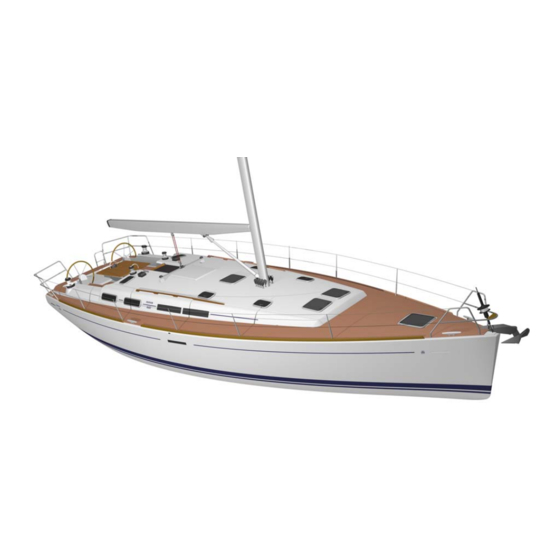
Page 28: Presentation Plan
EN G LI S H 2 2 - 0 4 - 0 5 P a g e 2 8 D U F O U R 4 5 5... -
Page 29: Accommodation Layout
ACCOMMODATIONS fig.A Layout 3 cabins 2 heads fig.B Layout 4 cabins 3 heads EN G LI S H 2 2 - 0 4 - 0 5 P a g e 2 9 D U F O U R 4 5 5... -
Page 30: Deck Fittings Plan
Rep. Description Rep. Description 42 Handle pocket 1 Stemhead fitting Stanchion with strut * 2 Stay chain plate Folding chain plate * 3 Chain anti-chafe plate 4 Bow rail 45 Handrail cockpit table 5 Stainless steel deflector Stainless Lifelines (set) Stem protector * 47 Deck ventilator Dorade ventilation box + protection *... - Page 31 EN G LI S H 2 2 - 0 4 - 0 5 P a g e 3 1 D U F O U R 4 5 5...
-
Page 32: Sail Plan
15·35 m 5·42 m 14·35 m 5·00 m LP (130%) 7·05 m Genoa area 55·0 m² Mainsail area 41·2 m² EN G LI S H 2 2 - 0 4 - 0 5 P a g e 3 2 D U F O U R 4 5 5... - Page 33 EN G LI S H 2 2 - 0 4 - 0 5 P a g e 3 3 D U F O U R 4 5 5...
-
Page 34: Halyard And Sheet Rigging Plan
Rep. Description standard mast 1 Simple swivel block & T 57 shackle 2 Fiddle block 3 Mainsail sheet - Light blue 4 Simple swivel block & T 75 shackle 5 Boom vang – Black 6 Rigid downhaul 7 Outhaul - White 8 Mainsail halyard –... - Page 35 EN G LI S H 2 2 - 0 4 - 0 5 P a g e 3 5 D U F O U R 4 5 5...
-
Page 36: 110V Circuit Diagram
Rep. Description Equipment Shore cable * Electrical box with main circuit breaker* Electrical panel with circuit breaker * Battery charger* Connection box* F Water heater G 110V outlets - 60Hz* Colours of electrical wiring b Light blue g Green m Brown n Black r Red v Green yellow... - Page 37 EN G LI S H 2 2 - 0 4 - 0 5 P a g e 3 7 D U F O U R 4 5 5...
-
Page 38: 220V Circuit Diagram
Rep. Description Equipment Shore cable * Electrical box with main circuit breaker* Electrical panel with circuit breaker * Battery charger* Connection box* F Water heater 220V outlets* Colours of electrical wiring b Light blue g Green m Brown n Black r Red v Green yellow w White... - Page 39 EN G LI S H 2 2 - 0 4 - 0 5 P a g e 3 9 D U F O U R 4 5 5...
-
Page 40: Charging And Power Circuit Diagram
Rep. Description Electric winch* Windlass control * (remote control) Remote control relay * Terminal strip Battery charger* 12VDC panel Single pole 100A circuit breaker* House batteries (2 as std) (4*) 125A fuse Battery switch 5A fuse* Alternator Splitter Starter motor Engine battery Engine battery switch Windlass relay *... - Page 41 EN G LI S H 2 2 - 0 4 - 0 5 P a g e 4 1 D U F O U R 4 5 5...
-
Page 42: 220 V Electrical Panel Diagram
Description Protection Navigation light Steaming light Mooring light Deck light LIGHTS Lighting stern area Saloon lights 2 Bow lights Fresh water pump Bilge pump Shower pump 12V outlet SERVICES Windlass Refrigerator Freezer Hi-Fi / Audio Navigation instrument pack Autopilot INSTRUMENTS Spare1 Spare 2 EN G LI S H 2 2 - 0 4 - 0 5... - Page 43 EN G LI S H 2 2 - 0 4 - 0 5 P a g e 4 3 D U F O U R 4 5 5...
-
Page 44: Electrical Panel Terminal Diagram
Rep. Description - Battery negative + Battery positive C1 Navigation light and compass C2 Steaming light C3 Mooring light C4 Deck light C5 Stern Cab. lighting and head C6 Saloon lights C7 Bow Cab. lighting and head C8 Fresh water pump C9 Bilge pump C10 Shower drain pump(s) C11 Fridge thermostat relay... - Page 45 EN G LI S H 2 2 - 0 4 - 0 5 P a g e 4 5 D U F O U R 4 5 5...
-
Page 46: Electrical Installation Drawing
Rep. Description 1 Port navigation light 2 Starboard navigation light Windlass * Windlass relay* 4 Swivelling spot 5 Bulkhead light + switch 6 Head bulkhead light + switch 7 Adjustable reading light HI FI/radio CD speaker Cockpit speaker * 10 Chart reading light 11 12V electrical panel 12 12V outlet 13 Refrigerator... - Page 47 EN G LI S H 2 2 - 0 4 - 0 5 P a g e 4 7 D U F O U R 4 5 5...
-
Page 48: 220 V Electrical Installation Drawing
Rep. Description 220V ( or 110V ) outlet * 2 Water-heater Battery charger * Main circuit breaker* Shore cable * Electrical panel * Microwave plug * * Option EN G LI S H 2 2 - 0 4 - 0 5 P a g e 4 8 D U F O U R 4 5 5... - Page 49 EN G LI S H 2 2 - 0 4 - 0 5 P a g e 4 9 D U F O U R 4 5 5...
-
Page 50: Steering System Drawing
Rep. Description 1 Emergency tiller 2 Steering wheel (2) 3 Compass (x2 Mill.06) 4 Rudder stop 5 Helm shaft 6 Blade + spindle 7 Trust bearing 8 Nylon grommet 9 Upper and lower bearings 10 Rudder post 11 Tiller deck plate Pilot chain Auto-pilot motor * Automatic pilot gear *... - Page 51 EN G LI S H 2 2 - 0 4 - 0 5 P a g e 5 1 D U F O U R 4 5 5...
-
Page 52: Gas System Diagram
Rep. Description 1 Gas tank ** 2 Valve tap ** 3 Regulator 4 Medium length connection hose 5 Spacer piece / 6x8 pipe 6 Watertight bulkhead grommet 7 PVC pipe 8 6x8 copper pipe 9 CE gas shut-off valve (in compartment under stove / oven) 10 Long length connection hose 11 3 burner stove / oven... - Page 53 EN G LI S H 2 2 - 0 4 - 0 5 P a g e 5 3 D U F O U R 4 5 5...
-
Page 54: Abandon Ship Plan
Rep. Description EXIT Exit Ex Recommended fire-extinguisher location 1 Under navigator's desk ** 2 Under square seating ** Engine compartment extinguishing hole ** Not supplied EN G LI S H 2 2 - 0 4 - 0 5 P a g e 5 4 D U F O U R 4 5 5... - Page 55 EN G LI S H 2 2 - 0 4 - 0 5 P a g e 5 5 D U F O U R 4 5 5...
-
Page 56: Fresh Water System Diagram
Rep. Description 1 Filler deck plate 2 Filler hose 3 Vent 4 Vent hose 5 Bow water tank 6 Cold water pipe 7 2 way manifold 8 Shower mixer tap 9 Water pump unit 10 Fresh water pump Hot-water tank/engine heat exchanger pipe 12 Water-heater 13 Combination fitting... - Page 57 EN G LI S H 2 2 - 0 4 - 0 5 P a g e 5 7 D U F O U R 4 5 5...
-
Page 58: Drainage System Diagram
Rep. Description Electric bilge pump 1 Strainer 2 Ø20 discharge hose 3 Electric bilge pump 4 Skin fitting Manual bilge pump 5 Strainer 6 Ø25 discharge hose 7 Manual bilge pump 8 Skin fitting EN G LI S H 2 2 - 0 4 - 0 5 P a g e 5 8 D U F O U R 4 5 5... - Page 59 EN G LI S H 2 2 - 0 4 - 0 5 P a g e 5 9 D U F O U R 4 5 5...
-
Page 60: Skin Fitting Location Diagram
Rep. Description Ø Skin fittings + seacocks 1 Galley sink discharge 1" 2 Washbasin discharge 1" 3 Toilet sea water intake 3/4" 4 Toilet discharge 1"1/4 5 Holding tank discharge * 2" 6 Foot pump sea water intake* 1/2" 7 Shower outlet 3/4"... - Page 61 EN G LI S H 2 2 - 0 4 - 0 5 P a g e 6 1 D U F O U R 4 5 5...
-
Page 62: Engine Installation Drawing
Rep. Description General 1 Propulsion engine 2 S-drive 3 Engine raw water pump 4 Polyester chassis 5 Engine controls panel (Starboard) 6 Propeller 7 Anode Cooling / Exhaust system 8 Sea water valve 10 Raw water strainer 11 Anti-siphon swan neck 12 Waterlock silencer 13 Exhaust pipe 14 Exhaust outlet... - Page 63 EN G LI S H 2 2 - 0 4 - 0 5 P a g e 6 3 D U F O U R 4 5 5...
-
Page 64: Holding Tank Fitting Drawing - Layout 3 Cabins
Rep. Description Layout 2 cabins 1 Skin fittings & 3/4" seacock 2 Skin fittings & 1"1/4 seacock 3 Skin fittings & 2" seacock * 4 Ø20 hose 5 38 mm Ø anti-odour hose * 6 51 mm Ø anti-odour hose * 7 3-way 38 mm Ø... - Page 65 EN G LI S H 2 2 - 0 4 - 0 5 P a g e 6 5 D U F O U R 4 5 5...
-
Page 66: Holding Tank Fitting Drawing - Layout 4 Cabins
Rep. Description Layout 3 cabins 1 Skin fittings & 3/4" seacock 2 Skin fittings & 1" 1/4 seacock 3 Skin fittings & 2" seacock * 4 Ø20 hose 5 38 mm Ø anti-odour hose * 6 51 mm Ø anti-odour hose * 7 3-way 38 mm Ø... - Page 67 EN G LI S H 2 2 - 0 4 - 0 5 P a g e 6 7 D U F O U R 4 5 5...
Need help?
Do you have a question about the Grand Large 455 and is the answer not in the manual?
Questions and answers