Advertisement
Advertisement

Related Manuals for Dufour Yachts Dufour 385


Summary of Contents for Dufour Yachts Dufour 385
- Page 1 OWNER’S MANUAL D U F O U R 3 8 5 EN G LI S H M A I 2 0 0 4...
- Page 2 Your dealer Name is DUFOUR YACHTS' representative and will give you all the help you need to solve any problems you might have during launching, stepping the mast or with technical checks for bringing your boat into service and maintaining it. If necessary, he will help you with the administrative process of registering your boat.
-
Page 3: Table Of Contents
CONTENTS INTRODUCTION___________________________________________________________________________ 5 GENERAL INFORMATION ______________________________________________________________ 6 Design category of the yacht __________________________________________________________ 6 Certification _______________________________________________________________________ 6 Identification ______________________________________________________________________ 6 Builder plate _______________________________________________________________________ 7 II. MAIN CHARACTERISTICS ______________________________________________________________ 8 III. ELECTRICAL SYSTEMS ________________________________________________________________ 9 Safety and operating instructions for the electrical system _________________________________ 9 Installing new equipment ____________________________________________________________ 9 Batteries _________________________________________________________________________ 10 Electric winch _____________________________________________________________________ 10... - Page 4 Presentation plan ______________________________________________________________________ 26 II. Interior layout plans ____________________________________________________________________ 27 III. Deck fittings plan ______________________________________________________________________ 28 IV. Sail plan______________________________________________________________________________ 30 Halyard and sheet rigging plan ___________________________________________________________ 32 VI. 110 V circuit diagram ___________________________________________________________________ 34 VII. 220 V circuit diagram ___________________________________________________________________ 36 VIII.
-
Page 5: Introduction
DUFOUR YACHTS is delighted to present you with this manual that will enable you to get to know your boat better. This manual has been produced to help you enjoy the use of your boat in complete safety. Read it carefully, in particular to avoid fire and flooding risks, and familiarize yourself with your boat before using it. -
Page 6: General Information
This sailing capability is equally dependent on the skills of the crew, their physical capacities, the maintenance of the boat and its equipment. So always take care before putting to sea. DUFOUR YACHTS is not able to guarantee perfect functioning of the boat in exceptional sea conditions (violent storms, hurricanes, cyclones, waterspouts,...) DESIGN CATEGORIES... -
Page 7: Builder Plate
It explains some essential information in which you find LA ROCHELLE details below. 0609 DUFOUR 385 Cat . de Concept i o n / Concept Cl a ss: A Nbre passagers / Max. passengers: Charge maxi / Max. load (kg) :... -
Page 8: Main Characteristics
Model DUFOUR 385 Architect: Umberto Felci Navigation category CE certification number CE/0609 Length over all 11.72 m Hull length 11.36 m Waterline length 9.84 m Maximum width 3.93 m Draft 1.76 m Air draft 16.20 m Ballast weight 1950 kg Empty weight (incl. -
Page 9: Electrical Systems
WARNING Always: - Check the condition of the batteries (charge and electrolyte level) and the charging system before putting to sea - Disconnect and remove batteries for winterisation - Do not let battery voltage drop below 10,5V during winter storage. - Carry spare lamps for all navigation lights and interior lighting. -
Page 10: Batteries
The battery capacity has been designed to meet the power requirements of the on-board accessories. To avoid any problems, it is necessary to keep a close eye on the maintenance and correct charging of the batteries. WARNING When installing new electrical appliances, take care that the overall consumption of these appliances remains within the capacity of your batteries. - Page 11 WARNING To avoid electric shocks or fire : - Switch off the shore supply at the on-board isolator before connecting or disconnecting the shore/boat supply cable. - Connect the shore/boat supply cable at the boat end before connecting it to the shore outlet - Disconnect the shore/boat supply cable at the shore outlet before disconnecting it at the boat end...
-
Page 12: Gas Installation
Read the instructions for the cooker and regulator carefully. Ensure that the gas cylinder and regulator are in accordance with the requirements of the cooker (flow rate, pressure, type of gas) and that the gas cylinder complies with the regulations in force in the country where it is being used. Shut off all appliance valves before opening the bottle valve. -
Page 13: Checking The System
The gas system must be tested periodically: °Close all the cooker taps. °Open the cooker supply and regulator valves. °Check all connections are gas-tight using a leak detector or by applying soapy water. WARNING ! Do not use solutions containing ammonia DANGER ! Never use a naked light to look for leaks Repairs and modifications to the system should be carried out by a qualified person. -
Page 14: Drain And Sanitation System
Pump type Theoretical flow rate Manuel 40.5 l / 45 strokes/min. Electric 900 l / h Read carefully the operating and maintenance instructions for the bilge pump that goes with your boat. WARNING ! Ensure that bilge pumps are in working order before putting to sea. Know where to find the hand pump and its handle. -
Page 15: Seacocks
Seacocks are of the 1/4-turn type: OPEN position: handle in line with seacock body, CLOSED position: handle perpendicular to seacock body. OPEN CLOSED WARNING ! Never interfere with the tightening of the sea cocks to the hull. In the event of a leak, consult a professional. -
Page 16: Flooding
Boat flooding risks: - Before putting to sea, always check that portholes, deck hatches and any other openings that could allow flooding are shut. -When under sail, close all seacocks, except the engine water intake. - Periodically check: - Skin fittings, seacocks and pipes are watertight - Proper emptying of the cockpit drains. -
Page 17: Safety Instructions
WARNING It is the responsibility of the owner/ captain to : have fire extinguishing equipment checked in accordance with the stipulations of the builder and the regulations in your country. Replace fire extinguishing equipment if it has expired or been discharged, by extinguishers of equal or greater capacity. -
Page 18: Engine
Regular maintenance must be carried out in accordance with the engineer's recommendations. Read carefully the engine operating instructions that come with the boat. Do not hesitate to consult your agent or a qualified professional. WARNING Ensure Ensure that the cooling circuit water intake seacock is open, and that water is coming out of the engine exhaust. -
Page 19: Winterisation
Modify the installation, unless this is carried out by a technician qualified in this field. The steering system plays a vital role in the safety and comfort of your boat. The Dufour 385 is fitted with a double wheel and a system of rudder cables and chains. Periodic checks to be performed: - Check the play in the various components (rudder stock/bearings, rudder cable tension and wear). -
Page 20: Emergency Tiller
WARNING - The Dufour 385 is equipped with an emergency tiller that must be kept readily accessible, we advise you to stow it in a cockpit locker near the tiller deck plate. - It is only designed for sailing at reduced speed in the event of damage to the helm. -
Page 21: Lightning Protection
Your boat is protected against lightning. The rigging is electrically connected to earth. Nonetheless, for your safety, it is necessary to respect certain precautions. If the boat has been struck by lightning: - the protection installation must be inspected to detect physical damage and check the integrity of the device, as well as the continuity of the earthing. -
Page 22: Safety Equipment
There is no harmonization of obligatory safety equipment across the European Community. You should seek information about national requirements for CE-marked boats. In France, yachts bearing the CE mark must carry the facilities and safety equipment stipulated for the category of sailing chosen by the yachtsman within the following limits: Design Category Possible sailing categories 1.2.3.4.5.6... -
Page 23: Handling, Transporting, Lift Out
When craning, take care that the slings are correctly positioned and are not fouling the propeller, the saildrive or a fragile sensor. Lifting frames should be wide enough, or fitted with spreaders to avoid exerting excessive lateral pressure on the rubbing band. Avoid letting slings foul the lifelines. - Page 24 PLANS DUFOUR 385 EN G LI S H M A Y 2 0 0 4 P a g e 2 4 D U F O U R 3 8 5...
- Page 25 Presentation plan ______________________________________________________________________ 26 II. Interior layout plans ____________________________________________________________________ 27 III. Deck fittings plan ______________________________________________________________________ 28 IV. Sail plan______________________________________________________________________________ 30 Halyard and sheet rigging plan ___________________________________________________________ 32 VI. 110 V circuit diagram ___________________________________________________________________ 34 VII. 220 V circuit diagram ___________________________________________________________________ 36 VIII.
-
Page 26: Presentation Plan
EN G LI S H M A Y 2 0 0 4 P a g e 2 6 D U F O U R 3 8 5... -
Page 27: Interior Layout Plans
AMENAGEMENT fig.A 3 cabin + 2 toilet version fig.B 3 cabin + 1 toilet version fig.C 2 cabin + 1 toilet version EN G LI S H M A Y 2 0 0 4 P a g e 2 7 D U F O U R 3 8 5... -
Page 28: Deck Fittings Plan
Rep. Description Number Rep. Description Number 42 Winch handle holder 1 Bow fitting 2 Forestay chainplate Reinforced stanchion for life line gate* 3 Rubbing plate Folding pad eye * Support for bowsprit pole * 4 Port pulpit Folding pad eye * 5 Starboard pulpit Bow protection plate * 47 Deck vent... - Page 29 EN G LI S H M A Y 2 0 0 4 P a g e 2 9 D U F O U R 3 8 5...
-
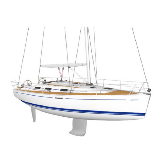
Page 30: Sail Plan
14.025 m 4.39 m 12.80 m 4.25 m 6.15 m Genoa surface 42.6 m² Mainsail surface 31.5 m² EN G LI S H M A Y 2 0 0 4 P a g e 3 0 D U F O U R 3 8 5... - Page 31 EN G LI S H M A Y 2 0 0 4 P a g e 3 1 D U F O U R 3 8 5...
-
Page 32: Halyard And Sheet Rigging Plan
Rep. Description classic mast 1 Single block + swivel shackle 2 Fiddle block 3 Mainsail sheet - Ø12 - white/red 4 Fiddle block + cleat 5 Fiddle block 6 Boom downhaul - Ø12 - white/red Rigid boom vang * 8 Mainsail halyard - white/red 9 Adjusting line mainsail track car - white/red 10 Reef no. - Page 33 EN G LI S H M A Y 2 0 0 4 P a g e 3 3 D U F O U R 3 8 5...
-
Page 34: 110 V Circuit Diagram
Rep. Description Equipment Shore power connection* Electric box with main switch * Electric box with differential * Battery charger* Connecting box* F Water heater G 110V - 60Hz socket* Cable Colours b Light blue g Green m Brown n Black r Red v Green yellow w White... - Page 35 EN G LI S H M A Y 2 0 0 4 P a g e 3 5 D U F O U R 3 8 5...
-
Page 36: 220 V Circuit Diagram
Rep. Description Equipment Shore power connection * Electric box with main switch * Electric box with differential * Battery charger* Connecting box * F Water heater 220V sockets* Cable colours b Light blue g Green m Brown n Black r Red v Green yellow w White * Option... - Page 37 EN G LI S H M A Y 2 0 0 4 P a g e 3 7 D U F O U R 3 8 5...
-
Page 38: Charging And Power Circuit Diagram
Rep. Description Electric windlass* Remote control for windlass * Relay for windlass remote control * Electric panel with terminals Battery charger* 12V switch panel 80 Amp unipolar circuit breaker for windlass * Service batteries (2 as standard) (3*) Fuse 125A Service battery switch Fuse 5A* Alternator... - Page 39 EN G LI S H M A Y 2 0 0 4 P a g e 3 9 D U F O U R 3 8 5...
-
Page 40: 12V / 220 V Electric Switch Panel Diagram
Security Rep. Description level 1 Navigation light 2 Steaming light 3 Anchor light 4 Refrigerator 5 Saloon lights 6 Cabin lights 7 Water circuit 8 Bilge pump 9 Shower water evacuation pump 10 Navigation instruments 11 Autopilot 12 12V socket – HiFi EN G LI S H M A Y 2 0 0 4 P a g e 4 0 D U F O U R 3 8 5... - Page 41 EN G LI S H M A Y 2 0 0 4 P a g e 4 1 D U F O U R 3 8 5...
-
Page 42: Electric Panel Terminal Diagram
Rep. Description - Battery negative pole + Battery positive pole C1 Navigation lights and compass C2 Steaming light C3 Anchor light C4 Relay for refrigerator thermostat C5 Saloon lights C6 Cabin and toilet cabin lights C7 Water circuit C8 Bilge pump C9 Shower water evacuation pump C10 Navigation instruments* And reading light at chart table... - Page 43 EN G LI S H M A Y 2 0 0 4 P a g e 4 3 D U F O U R 3 8 5...
-
Page 44: Installation Drawing
Rep. Description 1 Port light 2 Starboard light 3 Windlass * Relay for windlass * 4 Adjustable spot light 5 Ceiling and interior light 6 Ceiling light toilet +interior 7 Bulkhead mounted light 8 Loudspeaker HiFi/radio CD * 10 Chart table reading light 11 12V switch panel 12 12V socket 13 Cooling circuit... - Page 45 EN G LI S H M A Y 2 0 0 4 P a g e 4 5 D U F O U R 3 8 5...
-
Page 46: 220 V Installation Drawing
Rep. Description 1 220V socket ( or 110V )* 2 Water heater 3 Battery charger * 4 General circuit breaker * 5 Shore power connection * 6 Electric box * * Option EN G LI S H M A Y 2 0 0 4 P a g e 4 6 D U F O U R 3 8 5... - Page 47 EN G LI S H M A Y 2 0 0 4 P a g e 4 7 D U F O U R 3 8 5...
-
Page 48: Steering Wheel Drawing
Rep. Description 1 Emergency tiller 2 Steering wheel (2) 3 Compass 4 Rudder stock stop 5 Rudder stock spindle 6 Rudder + stock 7 Bush 8 Nylon O-ring Higher and lower rudder bearings 10 Rudder stock shaft 11 Grab rail on console Autopilot chain * Autopilot engine * Autopilot sprocket *... - Page 49 EN G LI S H M A Y 2 0 0 4 P a g e 4 9 D U F O U R 3 8 5...
-
Page 50: Gas Circuit Diagram
Rep. Désignation 1 Gas cylinder ** 2 Gas cylinder valve ** 3 Expander ** 4 Connecting piece 5 Connection / size 6x8 6 Watertight through bulkhead fitting 7 Plastic piping 8 Copper conduit 6x8 9 CE gas tap (under the cooker/oven) 10 Long connecting pipe 11 2 burner cooker and oven ** Not supplied... - Page 51 EN G LI S H M A Y 2 0 0 4 P a g e 5 1 D U F O U R 3 8 5...
-
Page 52: Abandon Ship Plan
Rep. Description EXIT Emergency exit Ex Recommended space for extinguishers Under chart table ** Under saloon bench ** Access hole to engine compartment For extinguisher Not supplied EN G LI S H M A Y 2 0 0 4 P a g e 5 2 D U F O U R 3 8 5... - Page 53 EN G LI S H M A Y 2 0 0 4 P a g e 5 3 D U F O U R 3 8 5...
-
Page 54: Fresh Water Circuit Diagram
Rep. Description 1 Deck filler 2 Water infill 3 Vent 4 Ventilation piping 5 Front water tank 6 Cold water piping 7 2 way collector 8 Shower mixing tap 9 Pressurised water circuit 10 Sweet water filter Piping for hot water heat exchange through engine 12 water heater 13 Galley mixing tap... - Page 55 EN G LI S H M A Y 2 0 0 4 P a g e 5 5 D U F O U R 3 8 5...
-
Page 56: Drain System Diagram
Rep. Description Electric bilge pump 1 Strainer 2 Evacuation piping Ø20 3 Electric bilge pump 4 Deck outlet Manual bilge pump 5 Strainer 6 Evacuation piping Ø25 7 Manual bilge pump 8 Deck outlet EN G LI S H M A Y 2 0 0 4 P a g e 5 6 D U F O U R 3 8 5... - Page 57 EN G LI S H M A Y 2 0 0 4 P a g e 5 7 D U F O U R 3 8 5...
-
Page 58: Skin Fitting Location Drawing
Rep. Function Ø Skin fittings and valves 1 Galley sink evacuation 1" 2 Wash basin evacuation 1" 3 Toilet infill 3/4" 4 Toilet outlet 1"1/4 5 Holding tank outlet* 2" 6 Water foot pump infill * 1/2" 7 Shower water evacuation 3/4"... - Page 59 EN G LI S H M A Y 2 0 0 4 P a g e 5 9 D U F O U R 3 8 5...
-
Page 60: Engine Installation Drawing
Rep. Description General 1 Engine 2 Saildrive 3 Sea water pump for engine 4 Engine base in polyester 5 Engine control panel 6 Propeller 7 Anode Cooling circuit / Exhaust system 8 Sea water valve 9 Sea water piping 10 Sea water filter 11 Anti-siphon valve 12 Waterlock 13 Exhaust piping... - Page 61 EN G LI S H M A Y 2 0 0 4 P a g e 6 1 D U F O U R 3 8 5...
-
Page 62: Holding Tank Fitting Drawing
Rep. Description 2 cabin version 1 Skin fitting & valve 3/4" 2 Skin fitting & valve 1" 1/4 3 Skin fitting & valve 2" * 4 Piping Ø20 5 Anti odour piping Ø38 * 6 Anti odour piping Ø51 * 7 3 way valve in plastic Ø38 * 8 Holding tank in polyethylene * 9 Deck outlet in aluminium Ø50 *... - Page 63 EN G LI S H M A Y 2 0 0 4 P a g e 6 3 D U F O U R 3 8 5...
-
Page 64: Holding Tank Fitting Drawing In 3 Cabin Version
Rep. Description 3 cabin version 1 Through hull fitting & valve 3/4" 2 Through hull fitting & valve1" 1/4 4 Piping Ø20 5 Anti odour piping Ø38 * 6 Anti odour pipingØ51 * 3 way valve in plastic PVC Ø38 8 Holding tank in polyethylene * 9 Deck outlet in aluminium Ø50 * 10 Vent in brass *... - Page 65 EN G LI S H M A Y 2 0 0 4 P a g e 6 5 D U F O U R 3 8 5...
Need help?
Do you have a question about the Dufour 385 and is the answer not in the manual?
Questions and answers