Advertisement
Introduction
An electrically commutated motor (ECM) has an energy
saving capability for applications that do not require
the motor to always run at full speed. This enables the
equipment to reduce the speed of the motor.
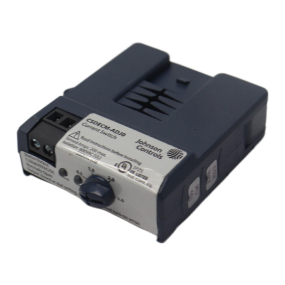
Figure 1: CSDECM-ADJ0 ECM Current Switch
Failure to follow these instructions can result in
death or serious injury.
Hazard of electrical shock, explosion, and arc flash.
Important:
• Follow all requirements in NFPA 70E for safe work
practices and for personal protective equipment
(USA) and other applicable local codes when you
install this product.
• Only qualified electrical personnel should install
this product.
• Read, understand, and follow all instructions
thoroughly.
• Install only on insulated conductors.
• Lock out and tag all power sources prior to
installation. Use a correctly rated voltage sensing
instrument to determine that no voltage is
present.
Failure to follow these instructions may result in
death or serious injury.
Automated equipment may start without warning.
CSDECM-ADJ Series ECM Adjustable Current
DANGER
WARNING
Switch Installation Guide
Equipment monitored or operated by this device may start
without warning. Keep clear of apparatus at all times.
Important:
• This product is not intended for life-safety
applications
• Do not install in hazardous or classified locations
• The installer is responsible for all applicable codes
• You must install this product in a suitable electrical
enclosure
Calibration and operation
The standby current draw of an ECM from the on-board
electronics ranges from 250 mA to 500 mA and varies by
manufacturer. This standby current can sometimes cause
a sensitive current sensor to be ON even when the motor
is not running, which gives a false indication. To prevent
this, the turn-on current of the current sensor must be
higher than the ECM standby current.
The Johnson Controls
adjustable turn-on ECM Current
®
Switch enables you to set or adjust the appropriate turn-
on threshold for your application. Set the dial so that the
turn-on current is slightly higher than the ECM standby
current.
Figure 2: ECM sensor output
Callout
Description
A
ECM monitored load
B
ECM sensor setpoint, adjustable to prevent
detection of standby current
C
Energized
D
Sensor output
E
Unloaded ECM inverter, for example 120 mA
On startup, the sensor output closes when the monitored
current exceeds the dial setting, and opens if the
monitored current is below the dial setting minus the
fixed hysteresis value of the current switch. For motors
with an expected running current of 0.5 A or less, you
may need several wraps of the conductor to enable the
CT to adequately read the difference between the standby
current and a run state.
LIT-12013530
2023-02-02
CSDECM, CRCSDP
Advertisement
Table of Contents

Related Manuals for Johnson Controls CSDECM-ADJ Series


Summary of Contents for Johnson Controls CSDECM-ADJ Series
- Page 1 CSDECM-ADJ Series ECM Adjustable Current Switch Installation Guide LIT-12013530 2023-02-02 Introduction Equipment monitored or operated by this device may start without warning. Keep clear of apparatus at all times. An electrically commutated motor (ECM) has an energy Important: saving capability for applications that do not require the motor to always run at full speed.
-
Page 2: Installation
Figure 3: Wiring Disconnect, lock out, and tag out all power supplies during installation. To install the CSDECM-ADJ Series ECM Adjustable Current Switch, complete the following steps: Determine the mounting location for the sensor near the conductor to be monitored. Locate the sensor at least 0.5 in. -
Page 3: Troubleshooting
The dial is a continuous sweep that enables fine-tuning. To set up the CSDECM-ADJ Series ECM Adjustable Current Switch, complete the following steps: When installed on the ECM conductor with the motor stopped but powered on, verify the open LED is on. -
Page 4: Technical Specifications
The performance specifications are nominal and conform to acceptable industry standard. For application at conditions beyond these specifications, consult the local Johnson Controls office. Johnson Controls shall not be liable for damages resulting from misapplication or misuse of its products. -
Page 5: Software Terms
GLENDALE, WI 53209 NO. 32 CHANGJIANG RD NEW THE NETHERLANDS MANCHESTER DISTRICT M40 2WL WUXI JIANGSU PROVINCE 214028 UNITED KINGDOM CHINA Contact information Contact your local Johnson Controls representative: www.johnsoncontrols.com/locations Contact Johnson Controls: www.johnsoncontrols.com/contact-us CSDECM-ADJ Series ECM Adjustable Current Switch Installation Guide... - Page 6 © 2023 Johnson Controls. All rights reserved. All specifications and other information shown were current as of document revision and are subject to change without notice. www.johnsoncontrols.com...
Need help?
Do you have a question about the CSDECM-ADJ Series and is the answer not in the manual?
Questions and answers