Sign In
Upload
Download
Table of Contents
Contents
Add to my manuals
Delete from my manuals
Share
URL of this page:
HTML Link:
Bookmark this page
Add
Manual will be automatically added to "My Manuals"
Print this page
×
Bookmark added
×
Added to my manuals
Manuals
Brands
ELTEX Manuals
Network Router
ME Series
Installation and quick start manual
ELTEX ME Series Installation And Quick Start Manual
Hide thumbs
1
Table Of Contents
2
3
4
5
6
7
8
9
10
11
12
13
14
15
16
17
18
19
20
21
22
23
24
25
26
27
28
29
30
31
32
page
of
32
Go
/
32
Contents
Table of Contents
Bookmarks
Table of Contents
Table of Contents
Abstract
Design
ME5100S, ME5100 Rev.X, ME5200S Front Panel
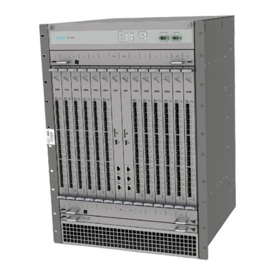
ME5000, ME5000M (Chassis) Front Panel
LC18XGE Line Card
LC20XGE Line Card
LC8XLGE Line Card
FMC16 Fabric and Management Card
FMC32 Fabric and Management Card
ME5100S, ME5100 Rev.X, ME5200S Rear Panel
ME5000, ME5000M Rear Panel
Light Indication
ME5100S, ME5100 Rev.X, ME5200S Light Indication
ME5000, ME5000M (Chassis) Light Indication
LC18XGE Line Card Light Indication
LC20XGE Line Card Light Indication
LC8XLGE Line Card Light Indication
FMC16 Card Light Indication
FMC32 Card Light Indication
Installation and Connection
Support Brackets Mounting
ME5100S, ME5100 Rev.X, ME5200S Rack Mounting
Power Module Installation
МЕ5000, ME5000M Chassis Mounting
Connection to Power Supply
Router Factory Settings
Connection to Command Line Interface (Cli)
Basic Router Configuration
Changing Admin Password
Creating New Users
Assigning Device Name
Configuring Access to a Management Network Via MGMT Interface
Applying Basic Settings
Resetting the Device to Factory Configuration Using F Function Key
Advertisement
Quick Links
Download this manual
ME Series Routers
ME5000, ME5000M, ME5100S, ME5100 rev.X, ME5200S
Installation and Quick Start Guide
Firmware version 3.0.0
Table of
Contents
Previous
Page
Next
Page
1
2
3
4
5
Advertisement
Table of Contents
Need help?
Do you have a question about the ME Series and is the answer not in the manual?
Ask a question
Questions and answers
Related Manuals for ELTEX ME Series
Network Router ELTEX ME5000 Installation And Quick Start Manual
(32 pages)
Network Router ELTEX ME5000M Installation And Quick Start Manual
(32 pages)
Network Router ELTEX ME5100S Installation And Quick Start Manual
(32 pages)
Network Router ELTEX ME5100 rev.X Installation And Quick Start Manual
(32 pages)
Network Router ELTEX ME5200S Installation And Quick Start Manual
(32 pages)
Network Router ELTEX ESR-100 Quick Start And Installation Manual
Esr series (19 pages)
Network Router ELTEX ESR-100 Operation Manual
Esr series (109 pages)
Network Router ELTEX NTU-2V Operation Manual
Optical network terminals (72 pages)
Network Router ELTEX RG-34-Wac User Manual
Subscriber router (51 pages)
Network Router ELTEX ESR-15V User Manual
(650 pages)
Network Router ELTEX ESR Series User Manual
Service routers (66 pages)
Network Router ELTEX ESR Series User Manual
Service routers (575 pages)
Network Router ELTEX NTU-RG-54 Series User Manual
Optical network terminals (69 pages)
This manual is also suitable for:
Me5000
Me5000m
Me5100s
Me5100 rev.x
Me5200s
Table of Contents
Print
Rename the bookmark
Delete bookmark?
Delete from my manuals?
Login
Sign In
OR
Sign in with Facebook
Sign in with Google
Upload manual
Upload from disk
Upload from URL


Need help?
Do you have a question about the ME Series and is the answer not in the manual?
Questions and answers