
Related Manuals for ELTEX ESR Series


Summary of Contents for ELTEX ESR Series
- Page 1 ESR series service routers ESR-10, ESR-12V, ESR-12VF, ESR-14VF, ESR-20, ESR-21, ESR-100, ESR-200, ESR-1000, ESR-1200, ESR-1500, ESR-1510, ESR-1700 User manual, Hardware description (08.11.2019) Firmware version 1.8.2...
-
Page 2: Table Of Contents
Hardware description Содержание Introduction ..........................4 Abstract ............................4 Target Audience........................4 Notes and warnings.........................4 Product Description .........................5 Purpose ............................5 Functions..........................5 2.2.1 Interfaces functions......................5 2.2.2 Functions for MAC address processing................5 2.2.3 Second-layer functions of OSI model ................6 2.2.4 Third-layer functions of OSI model ..................6 2.2.5 Traffic tunnelling functions ....................7 2.2.6... - Page 3 Hardware description Management interfaces ....................... 52 Command Line Interface (CLI)..................... 52 Types and naming procedure of router interfaces ............. 52 Types and naming procedure of router tunnels..............55 Initial router configuration....................56 ESR router factory settings ....................56 5.1.1 Description of factory settings..................56 Router connection and configuration ..................
-
Page 4: Introduction
Devices provide high performance and bandwidth, and feature protection of transmitted data. This operation manual describes intended use, specifications, features, design, installation, first time setup, and firmware update guidelines for the ESR series service router (next, the router or the device). 1.2 Target Audience... -
Page 5: Product Description
Hardware description 2 Product Description 2.1 Purpose ESR series devices are the high performance multi-purpose network routers. Device combines traditional network features with a complex multi-tier approach to routing security, and ensures robust corporate environment protection. Device has a built-in firewall that enables protection of your and organization network environment and supports latest data security, encryption, authentication and anti-intrusion features. -
Page 6: Second-Layer Functions Of Osi Model
Hardware description Learning MAC address table may contain either static addresses or addresses learnt during data packet transition mode through the device. Learning involves registration of packet source MAC addresses with their binding to ports and VLANs. Afterwards, this data is used for incoming packet routing. Registered MAC address lifetime is limited. Administrator may adjust this setting. -
Page 7: Traffic Tunnelling Functions
Hardware description DHCP client DHCP (Dynamic Host Configuration Protocol) protocol enables automation of the network device management process. DHCP client allows the router to obtain the network address and additional settings from the external DHCP server. As a rule, this method is used for obtaining network settings of a public network operator (WAN). - Page 8 Hardware description Configuration file download and upload Device parameters are saved into the configuration file that contains configuration data for the specific device ports as well as for the whole system. The following protocols may be used for file transfers: TFTP, FTP, and SCP.
-
Page 9: Network Security Functions
Hardware description 2.2.7 Network security functions Table 7 lists network security functions of the device. Table 7 – Network security functions Security zones All router interfaces are distributed by security areas. For each zone pair, you can set the rules that determine the possibility of data transmission between zones, data traffic filtering rules. - Page 10 Hardware description Interfaces ESR-1700 4 x Ethernet 10/100/1000BASE-T/1000BASE-X Combo 8 x 10GBASE-R/1000BASE-X (SFP+/SFP) ESR-1510 4 x Ethernet 10/100/1000BASE-T 4 x Ethernet 10/100/1000BASE-T/1000BASE-X Combo 4 x 10GBASE-R/1000BASE-X (SFP+/SFP) ESR-1500 4 x Ethernet 10/100/1000BASE-T 4 x Ethernet 10/100/1000BASE-T/1000BASE-X Combo 4 x 10GBASE-R/1000BASE-X (SFP+/SFP) ESR-1200 12 x Ethernet 10/100/1000BASE-T 4 x Ethernet 10/100/1000Base-T/1000BASE-X Combo...
- Page 11 Hardware description ESR-10 4 x Ethernet 10/100/1000BASE-T, 2 x 1000BASE-X Types of optical transceivers ESR-1700 1000BASE-X SFP, 10GBASE-R SFP+ ESR-1510 ESR-1500 ESR-1200 ESR-1000 ESR-200 1000BASE-X SFP ESR-100 ESR-21 ESR-20 ESR-14VF ESR-12V(F) ESR-10 Duplex or half-duplex interface modes • duplex and half-duplex modes for electric ports •...
- Page 12 Hardware description ESR-200 • electrical interfaces 10/100/1000 Mbps • optical interfaces 1 Gbps ESR-100 ESR-21 ESR-20 ESR-14VF ESR-12V(F) ESR-10 MAC table ESR-1700 128k entries ESR-1510 ESR-1500 ESR-1200 ESR-1000 16k entries ESR-200 2k entries per bridge ESR-100 ESR-21 ESR-20 ESR-14VF ESR-12V(F) ESR-10 VLAN support...
- Page 13 Hardware description Quantity of L3 ESR-1700 4000 interfaces ESR-1510 ESR-1500 ESR-1200 ESR-1000 ESR-200 ESR-100 ESR-21 ESR-20 ESR-14VF ESR-12V(F) ESR-10 Quantity of BGP routes ESR-1700 2,8M ESR-1510 ESR-1500 ESR-1200 ESR-1000 ESR-200 1,5M ESR-100 ESR-21 ESR-20 ESR-14VF 800k ESR-12V(F) ESR-10...
- Page 14 Hardware description Quantity of OSPF routes ESR-1700 500k ESR-1510 ESR-1500 ESR-1200 ESR-1000 ESR-200 300k ESR-100 ESR-21 ESR-20 ESR-14VF ESR-12V(F) ESR-10 Quantity of RIP routes Quantity of static routes FIB size ESR-1700 1,7M ESR-1510 ESR-1500 ESR-1200 ESR-1000 ESR-200 1,5M ESR-100 ESR-21 ESR-20 ESR-14VF...
- Page 15 Hardware description Compliance IEEE 802.3 10BASE-T Ethernet IEEE 802.3u 100BASE-T Fast Ethernet IEEE 802.3ab 1000BASE-T Gigabit Ethernet IEEE 802.3z Fiber Gigabit Ethernet ANSI/IEEE 802.3 автоопределение скорости IEEE 802.3x контроль потоков данных IEEE 802.3ad объединение каналов LACP IEEE 802.1Q виртуальные локальные сети VLAN IEEE 802.1v IEEE 802.3ac IEEE 802.3ae...
- Page 16 Hardware description ESR-200 AC: 220V+-20%, 50Hz ESR-100 ESR-21 ESR-20 ESR-14VF ESR-12V(F) ESR-10 AC: 220V Maximum power ESR-1700 250 W consumption ESR-1510 160 W ESR-1500 ESR-1200 85 W ESR-1000 75 W ESR-200 25 W ESR-100 20 W ESR-21 25 W ESR-20 ESR-14VF 27 W...
- Page 17 Hardware description ESR-200 2.5 kg max ESR-100 ESR-21 3.15 kg max ESR-20 2 kg max ESR-14VF 1 kg max ESR-12V(F) ESR-10 Dimensions ESR-1700 440x490x88 mm ESR-1510 430x425x44 mm ESR-1500 ESR-1200 430x352x44 mm ESR-1000 ESR-200 310х240х44 mm ESR-100 ESR-21 430х225х44 mm ESR-20 267х212х44 mm ESR-14VF...
-
Page 18: Design
Hardware description о Operating temperature ESR-1700 from -10 to +45 С range ESR-1510 ESR-1500 ESR-1200 ESR-1000 ESR-200 ESR-100 ESR-21 ESR-20 о ESR-14VF from 0 to +40 С ESR-12V(F) ESR-10 о Storage temperature range from -40 to +70 С Operation relative humidity (non- 80% max. - Page 19 Hardware description Figure 1 – ESR-1700 front panel Table 9 lists connectors, LEDs and controls located on the front panel of ESR-1700. Table 9 – Description of ESR-1700 connectors, LEDs and front panel controls № Front panel element Description HDD1 Connector for HDD installation.
- Page 20 Hardware description Front panel element Description № Functional key that reboots the device and resets it to factory default configuration: • Pressing the key for less than 10 seconds reboots the device; • Pressing the key for more than 10 seconds resets the terminal to factory settings.
-
Page 21: Esr-1510, Esr-1500 Design
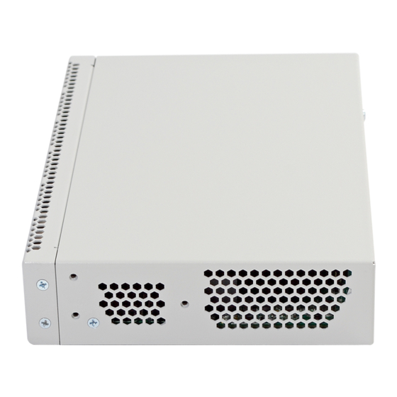
Hardware description Figure 4 – ESR-1700 left side panel Side panels of the device have air vents for heat removal. Do not block air vents. This may cause the components to overheat, which may result in device malfunction. For recommendations on device installation, see section Installation and connection. - Page 22 Hardware description № Front panel element Description Ethernet port for router management. SD-card connector. USB1 Port for USB device connection. Functional key that reboots the device and resets it to factory default configuration: • Pressing the key for less than 10 seconds reboots the device; •...
-
Page 23: Esr-1200, Esr-1000 Design
Hardware description ESR-1510, ESR-1500 side panels Figure 7 – ESR-1500, ESR-1510 right side panel Figure 8 – ESR-1500, ESR-1510 left side panel Side panels of the device have air vents for heat removal. Do not block air vents. This may cause the components to overheat, which may result in device malfunction. - Page 24 Hardware description № Front panel element Description Status Current device status LED. Alarm Alarm LED. НА operation mode indicator. Flash Activity indicator of exchange with data storages (SD-card or USB Flash). Power Device power LED. Master Indicator of failover modes operation. Fan operation LED.
- Page 25 Hardware description № Front panel element Description USB2 Port for USB device connection. XG1, XG2 Slots for 10G SFP+/1G SFP transceivers. [1 .. 24] 24 ports of Gigabit Ethernet 10/100/1000BASE-T (RJ-45). Status Current device status LED. Alarm Alarm LED. Active VPN sessions indicator.
-
Page 26: Esr-200, Esr-100 Design
Hardware description Table 15 lists rear panel connectors of the router. Table 15 – Rear panel connectors description № Description Main power supply. Place for installation of a redundant power supply. Hot-swappable removable ventilation modules. Earth bonding point of the device. ESR-1200, ESR-1000 side panels Figure 12 –... - Page 27 Hardware description Figure 15 – ESR-100 front panel Table 16 lists connectors, LEDs and controls located on the front panel of ESR-100 and ESR-200 routers. Table 16 – Description of connectors, LEDs and controls located on ESR-200, ESR-100 front panel Front panel element Description №...
-
Page 28: Esr-21 Design
Hardware description Figure 16 – ESR-200, 100, rear panel Table 17 lists rear panel connectors of the router. Table 17 – Rear panel connectors description № Description Earth bonding point of the device. Ventilation module. ESR-100, ESR-200 side panels Figure 17 –... - Page 29 Hardware description Table 18 – Description of connectors, LEDs and controls located on ESR-21 front panel № Front panel element Description 220V АC Power supply Power Device power LED Status Device status LED Alarm Device alarm presence and level LED HA operation mode LED (is not supported in the current version) Functional key that reboots the device and resets it to factory default configuration: pressi SD-card connector...
-
Page 30: Esr-20 Design
Hardware description Table 19 – Rear panel connectors description Description № Earth bonding point of the device. ESR-21 side panels The side panel layout of ESR-21 is depicted in figures 21 and 22. Figure 21 – ESR-21 left side panel Figure 22 –... - Page 31 Hardware description Table 20 – Description of connectors, LEDs and controls located on ESR-20 rear panel № Front panel element Description 110-250 VАC Power supply. Power Device power LED. Status Current device status LED. Alarm Alarm LED. HA operation mode LED (is not supported in the current version). Functional key that reboots the device and resets it to factory default configuration: pressi Console Console port for local management of the device.
-
Page 32: Esr-12Vf, Esr-14Vf Design
Hardware description Table 21 – Rear panel connectors description Description № Earth bonding point of the device. ESR-20 side panels The side panel layout of ESR-20 is depicted in figures 25 and 26. Figure 25 – ESR-20 left side panel Figure 26 –... - Page 33 Hardware description Table 22 – Description of connectors, LEDs and controls located on ESR-12VF, ESR-14VF front panel № Front panel element Description 220V АC Power supply. Power Device power LED. Console Console port RS-232 for local management of the device. Functional key that reboots the device and resets it to factory default configuration: pressi USB1, USB2 2 USB connectors for connecting external USB devices.
- Page 34 Hardware description ESR-14VF, ESR-12VF rear panel The rear panel layout of ESR-12VF, ESR-14-VF is depicted in figure 28. Figure 28 – ESR-12VF, ESR-14VF rear panel Table 23 lists rear panel connectors of the router. Table 23 – Rear panel connectors description Description №...
-
Page 35: Esr-12V Design
Hardware description 2.4.8 ESR-12V design The device has a metal housing available for 19” form-factor rack mount; housing size is 1U. ESR-12V front panel The front panel layout of ESR-12V is depicted in figure 31. Figure 31 – ESR-12V front panel Table 24 lists connectors, LEDs and controls located on the front panel of ESR-12VF router. - Page 36 Hardware description ESR-12V rear panel The rear panel layout of ESR-12V is depicted in 32. Figure 32 – ESR-12V rear panel Table 25 lists rear panel connectors of the router. Table 25 – Rear panel connectors description Description № Earth bonding point of the device.
-
Page 37: Esr-10 Design
Hardware description 2.4.9 ESR-10 design ESR-10 rear panel The rear panel layout of the device is depicted in figure 35. Figure 35 – ESR-10 rear panel Table 26 lists connectors, LEDs and controls located on the rear panel of ESR-10. Table 26 –... - Page 38 Hardware description Figure 36 – ESR-10 side panel Table 27 lists right panel controls of the router. Table 27 – Right panel connectors description Side panel element Description № Functional key that reboots the device and resets it to factory default configuration: · ...
-
Page 39: Light Indication
Hardware description Table 28 – Description of front panel LEDs Top panel element Description № Power Device power and operation status LED The LED is not used USB1, USB2 External USB devices LED [1 .. 4] Ethernet ports LED [5 .. - Page 40 Hardware description Table 29 – Light indication of copper interface status SPEED indicator light LINK/ACT indicator light Ethernet interface state The port is disabled or connection is not established. Solid on 10Mbps or 100Mbps connection is established. Solid on Solid on 1000Mbps connection is established.
- Page 41 Hardware description Indicator Indicator function Device State name State Power Device power LED. Green Device power is OK. Main power supply, if installed, is operational. Orange Main power supply failure, fault, or the primary network is missing. Device internal power supply failure. Master Indicator of failover modes operation.
- Page 42 Hardware description Table 32 – Light indication of copper and SFP interface status SPEED indicator light LINK/ACT indicator light Ethernet interface state The port is disabled or connection is not established. Solid on 10Mbps or 100Mbps connection is established. Solid on Solid on 1000Mbps connection is established.
- Page 43 Hardware description Table 34 – Light indication of copper and SFP interface status SPEED indicator light LINK/ACT indicator light Ethernet interface state The port is disabled or connection is not established. Solid on 10Mbps or 100Mbps connection is established. Solid on Solid on 1000 Mbps connection is established.
- Page 44 Hardware description Indicator Indicator function Device State name State HA operation mode LED (is not supported in the current version) ESR-12V(F) light indication Gigabit Ethernet copper interface statuses are represented by two LEDs – green LINK/ACT LED and amber SPEED LED.
- Page 45 Hardware description Indicator name Indicator function LED State Device State Device internal power supply failure. ESR-10 light indication Gigabit Ethernet copper interfaces statuses are represented by amber SPEED LED.
-
Page 46: Delivery Package
Hardware description Table 38 – Light indication of copper interface status SPEED indicator light Ethernet interface state Port is disabled or connection is not established Solid on 1000Mbps connection is established Flashes Data transfer is in progress 2.5 Delivery Package ESR-10 standard delivery package includes: •... - Page 47 Hardware description ESR-200 standard delivery package includes: • ESR-200 router; • Power cable; • 19” rack mounting kit; • Documentation. ESR-1000 standard delivery package includes: • ESR-1000 router; • 19” rack mounting kit; • Documentation. ESR-1200 standard delivery package includes: •...
-
Page 48: Installation And Configuration
Hardware description 3 Installation and configuration This section describes installation of the device into a rack and connection to a power supply. 3.1 Support brackets mounting The delivery package includes support brackets for rack installation and mounting screws to fix the device case on the brackets. -
Page 49: Esr-1000, Esr-1200, Esr-1500, Esr-1510, Esr-1700 Power Module Installation
Hardware description Figure 46 – Device rack installation Device ventilation system is implemented using 'front-rear' layout. Vents are located on the front and side panels of the device; ventilation modules are located at the rear. Do not block air inlet and outlet vents to avoid components overheating and subsequent device malfunction. -
Page 50: Connection To Power Supply
Hardware description Figure 48 – Plug installation Power module fault indication may be caused not only by the module failure, but also by the absence of the primary power supply. You can check the state of power modules by the indication on the front panel of the router (see Section Light indication) or by diagnostics, available through the router management interfaces. -
Page 51: Transceiver Removal
Hardware description 2. Push the module into the device housing until it is secured with a clicking sound. Figure 50 – Installed SFP transceivers 3.5.2 Transceiver removal 1. Flip the module handle to unlock the latch. Figure 51 – Opening SFP transceiver latch 2. -
Page 52: Management Interfaces
Hardware description 4 Management interfaces You may use various management interfaces in order to control and monitor the device. To access the device, you may use network connection via Telnet or SSH as well as direct connection via RS-232 compliant console port. For Telnet, SSH or console port connections, the command line interface is used for device management. - Page 53 Hardware description Table 39 – Types and naming procedure of router interfaces Interface type Designation Physical interfaces Designation of physical interface includes its type and identifier. The identifier of physical interfaces is as follows: <UNIT>/<SLOT>/<PORT>, where: • <UNIT> – number of a device in a device group, •...
- Page 54 Hardware description Interface type Designation Q-in-Q interfaces Designation of Q-in-Q interface is generated from the designation of basic interface, service VLAN identifier and user VLAN identifier separated by a dot. Designation examples: • gigabitethernet 1/0/12.100.10 • tengigabitethernet 1/0/2.45.12 • port-channel 1.6.34 ...
-
Page 55: Types And Naming Procedure Of Router Tunnels
Hardware description 4.3 Types and naming procedure of router tunnels Network tunnels of various types and purposes are used for the router operation. The naming system allows you to uniquely address the tunnels by their functional purpose. The following table contains the list of tunnels types. -
Page 56: Initial Router Configuration
Hardware description 5 Initial router configuration 5.1 ESR router factory settings The device is shipped to the consumer with the factory configuration installed that includes essential basic settings. Factory configuration allows you to use the router as a gateway with SNAT without applying any additional settings. -
Page 57: Router Connection And Configuration
To enable network access to the router on the first startup, static IP address 192.168.1.1/24 has been configured on Bridge 1 interface. 5.2 Router connection and configuration ESR series routers are intended to perform border gateway functions and securing the user network when it is connected to public data networks. Basic router configuration should include: •... -
Page 58: Applying The Configuration Change
Hardware description If IP address is not obtained for some reason, assign the interface address manually using any address except for 192.168.1.1 in 192.168.1.0/24 subnet. RS-232 console port connection Using RJ-45/DBF9 cable included into device delivery package, connect the router 'Console' port to the computer RS-232 port. - Page 59 Hardware description Changing password for "admin" user To ensure the secure system access, you should change the password for the privileged 'admin' user. 'techsupport' account is required for service centre specialist remote access. 'remote' account – RADIUS, TACACS+, LDAP authentication. 'admin', 'techsupport', 'remote' users cannot be deleted.
- Page 60 Hardware description Example of commands, that allow you to create user 'fedor' with password '12345678' and privilege level 15 and create user 'ivan' with password 'password' and privilege level '1': esr# configure esr(config)# username fedor esr(config-user)# password 12345678 esr(config-user)# privilege esr(config-user)# exit esr(config)# username ivan esr(config-user)# password password...
- Page 61 Hardware description Provider may use dynamically assigned addresses in their network. If the there is DHCP server in the network, you can obtain the IP address via DHCP. Configuration example for obtaining dynamic IP address from DHCP server on GigabitEthernet 1/0/10 interface: esr# configure esr(config)#...
- Page 62 Hardware description esr# configure esr(config)# object-group network clients esr(config-addr-set)# ip address-range 132.16.0.5-132.16.0.10 esr(config-addr-set)# exit esr(config)# object-group network gateway esr(config-addr-set)# ip address-range 40.13.1.22 esr(config-addr-set)# exit esr(config)# object-group service ssh esr(config-port-set)# port-range esr(config-port-set)# exit esr(config)# security zone-pair untrusted self esr(config-zone-pair)# rule esr(config-zone-rule)# action permit esr(config-zone-rule)# match protocol tcp esr(config-zone-rule)# match source-address clients...
-
Page 63: Firmware Update
Hardware description 6 Firmware update 6.1 Updating firmware via system resources To update the firmware, use any of the following servers: TFTP, FTP, SCP. Router firmware files obtained from the manufacturer should be allocated on the server. The router stores two copies of the firmware. To ensure the reliability of the firmware update procedure, only the copy that was not used for the last device startup is available for the update. -
Page 64: Updating Firmware Via Bootloader
Hardware description esr# show bootvar Image Version Date Status After reboot ----- -------------- -------------------- ------------ ------------ 1.0.7 build 141[f812808] date 18/02/2015 time Active 16:12:54 1.0.7 build 141[f812808] date 18/02/2015 time Not Active 16:12:54 Use the following command to select the image: esr# boot system image-[1|2] To update the secondary bootloader (U-Boot), enter the following command: Specify IP address of the server being used as <server>... -
Page 65: Secondary Bootloader Update (U-Boot)
Hardware description Specify router IP address: BRCM.XLP316Lite Rev B0.u-boot# setenv ipaddr 10.100.100.2 и выше: BRCM.XLP316Lite Rev B0.u-boot# ipaddr 10.100.100.2 Для версии Specify the name of the frimware file on the TFTP server: и выше: BRCM.XLP316Lite Rev B0.u-boot# firmware_file firmware Для... - Page 66 Hardware description Configuring PoE... distribution dest_threshold drop_timer Configuring POE in bypass mode NAE configuration done! initializing port 0, type 2. initializing port 1, type 2. SMC Endian Test:b81fb81f nae-0, nae-1 =======Skip: Load SYS UCORE old 8xxB1/3xxB0 revision on default. Hit any key to stop autoboot: Specify TFTP server address: BRCM.XLP316Lite Rev B0.u-boot# setenv serverip 10.100.100.1...
Need help?
Do you have a question about the ESR Series and is the answer not in the manual?
Questions and answers