ELTEX ESR-100 Quick Start And Installation Manual
Esr series
Hide thumbs
Also See for ESR-100:
- Operation manual (109 pages) ,
- User manual (650 pages) ,
- User manual (575 pages)

Related Manuals for ELTEX ESR-100


Summary of Contents for ELTEX ESR-100
- Page 1 ESR series routers ESR-100, ESR-200, ESR-1000, ESR-1200 Quick start and installation guide Software version 1.2.0...
- Page 2 20.11.2015 Synchronization with firmware version 1.0.7. Version 1.3 18.08.2015 Synchronization with firmware version 1.0.6. ESR-100 and ESR-200 descriptions are added (Added descriptions of ESR-100 and ESR-200) Changes in chapters: 2 Alternate design 4 Factory default model of the router 6.4 Settings of public network (WAN) parameters Version 1.2...
-
Page 3: Table Of Contents
1. ANNOTATION .............................. 4 2. DESIGN ................................ 4 2.1. ESR-1000, ESR-1200 design ......................... 4 2.2. ESR-100 and ESR-200 designs ......................7 2.3. Light indication ............................ 9 3. CONNECTION TO POWER SUPPLY ......................12 4. ROUTER FACTORY DEFAULT MODEL ......................13 5. -
Page 4: Annotation
1. ANNOTATION This guide coverages instruction of connection to power supply, factory device configuration and basic ESR series router configuration recommendations (hereafter referred to as the device). The guide is destined for technical staff that performs installation, configuration and putting the device into operation. - Page 5 Master Indicator of failover modes operation. Fan alarm indicator. Backup power source indicator. Functional key that reboots the device and resets it to factory settings: Pressing the key for less than 10 seconds reboots the device; Pressing the key for more than 10 seconds resets the terminal to factory settings.
-
Page 6: Side Panel
ESR-1000, ESR-1200 back panel The back panel of ESR-1000/ESR-1200 is represented in figure 2.3 Figure 2.3 – Back panel of ESR-1000, ESR-1200 The list of connectors located on the back panel of ESR1000/1200 is described in Table 2.3. Table 2.3 – Description of connectors located on back panel of ESR-1000, ESR-1200 №... -
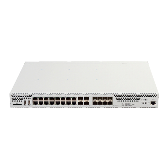
Page 7: Esr-100 And Esr-200 Designs
ESR-200 front panel Figure 2.7 - Front panel of ESR-200 The list of connectors, light indicators and controls that are located on the front panel of ESR-100, ESR-200 are described in the Table 2.4. Table 2.4 – Description of connectors, light indicators and controls located on the front panel of ESR-100, ESR-200 №... - Page 8 ESR-100 and ESR-200 back panels Figure 2.8 - Back panel of ESR-100, ESR-200 The list of connectors located on the back panel of ESR100/200 is described in Table 2.5 Table 2.5 – Description of connectors located on back panel of ESR-100, ESR-200 № Description Device earth bonding point.
-
Page 9: Light Indication
2.3. Light indication ESR-1000 light indication Metal interfaces state of GigabitEthernet is represented by two LED indicators: LINK/ACT - green and SPEED -amber: SPEED LINK/ACT Figure 2.11 - RJ-45 socket appearance SFP-interface status is represented by two RX/ACT and TX/ACT indicators: RX/ACT TX/ACT Figure 2.12 - Optical interfaces' indicators Table 2.6 - Light state indication of metal interfaces and SFP- interfaces... - Page 10 Table 2.8 - System indicator states Indicator Indicator functions Indicator state Device state name Green Device operates properly. Status Currency device indicator. Orange Device is in the software loading state Existence and device emergency Alarm level indicator Active VPN-session indicator. Indicator of active exchange with Carrying out read/write operation by Flash...
- Page 11 ESR-100 and ESR-200 light indication Metal interface states of GigabitEthernet and SFP-interfaces are represented by two LED indicators: LINK/ACT - green and SPEED - amber. Location of cooper interfaces indicators is depicted in the Figure 2.11. Location of SFP interfaces indicators is depicted in the Figure 2.13. Description of light indication is represented in the Table 2.9.
-
Page 12: Connection To Power Supply
3. CONNECTION TO POWER SUPPLY Ground the case of the device prior to connecting it to the power supply. An insulated multiconductor wire should be used for earthing. The device grounding and the earthing wire cross- section should comply with Electric Installation Code (EIC). If a PC or another device is supposed to be connected to the switch console port, the device should be also securely grounded. -
Page 13: Router Factory Default Model
IP-address from provider is opened in this area. All incoming connections from this area to the router are forbidden. The buffer zone includes the next interfaces: ESR-100/ESR-200: GigabitEthernet1/0/1; ESR-1000/ESR-1200: GigabitEthernet1/0/1, TengigabitEthernet1/0/1, TengigabitEthernet1/0/2. Area interfaces are integrated into one L2 segment by Bridge 2 network bridge. -
Page 14: Router Command Line Interface Connection (Cli)
5. ROUTER COMMAND LINE INTERFACE CONNECTION (CLI) 5.1. Ethernet local network connection The router loads with the factory configuration during the first start. Factory configuration is described in chapter 4 of the document. Step 1. Connect data transmission network cable (patch-cord) to any port of «trusted» area and to the computer assigned for management. -
Page 15: Router Basic Settings
6. ROUTER BASIC SETTINGS During the first connection, router settings procedure includes the next stages: 1. Changing of the user password («admin»). 2. New user creation. 3. Destination of the device name (Hostname). 4. Parameters settings of the connection to WAN in accodance with provider requirenments. 5. -
Page 16: Device Name Destination
6.3. Device name destination The next commands are used to assign device name: esr-1000# configure esr-1000(config)# hostname <new-name> After applying of the configuration, command prompt will be changed to value that is assigned by <new-name> parameter. 6.4. WAN parameters settings You need to assign device parameters determined by a provider (IP-address, subnet mask and gateway address by default) to adjust router network interface in public network (WAN). -
Page 17: Router Remote Configuration
IP address Interface Type ------------------- ------------ ------- 192.168.11.5/25 gi1/0/4 DHCP 6.5. Router remote configuration The default configuration has a remote access to the router via Telnet or SSH protocols from the «trusted» zones. To permit remote access from the other zone (for example, WAN) you need to create corresponding rules in Firewall. -
Page 18: Basic Setting Application
6.7. Checking the adjustment Try to get access to the website http://eltex.nsk.ru from the «trusted» zone for settings verification. If you got access it means traffic passes through a service router. If you didn’t get access – check settings verification. - Page 19 +7(383) 272-83-31 E-mail: techsupp@eltex.nsk.ru In official website of the Eltex Ltd. you can find technical documentation and software for products, advert to knowledge base, leave your interactive inquiry or ask for consultation from engineers of Service center in our technical forum: http://www.eltex.nsk.ru/en/support/downloads/...
Need help?
Do you have a question about the ESR-100 and is the answer not in the manual?
Questions and answers