
Subscribe to Our Youtube Channel
Related Manuals for ELTEX NTU-2V


Summary of Contents for ELTEX NTU-2V
- Page 1 NTU-2V(C) NTU-2W NTU-RG-1402G-W Operation Manual, Version 1.0 (17 April 2017) Optical Network Terminals IP address: http://192.168.1.1 User name: user Password: user http://eltex-co.ru/support/downloads/...
- Page 2 ____________________________________________________________________________________ Document Suitable Issue date Changes version firmware version Version 1.0 3.25.2.1593 17 April 2017 First issue NOTES AND WARNINGS Notes contain important information, tips, or recommendations on device operation and setup. Warnings inform users about hazardous conditions, which may cause injuries or device damage and may lead to the device malfunctioning or data loss.
-
Page 3: Table Of Contents
2.6.5 Reboot and Reset to Factory Settings ................22 Delivery Package ......................... 22 DEVICE ARCHITECTURE ........................23 NTU-2V(C) Architecture ......................23 NTU-2W Architecture ......................... 26 NTU-RG-1402G-W Architecture ....................29 NTU-RG-1402G-W CONFIGURATION VIA WEB INTERFACE. USER ACCESS ........33 The Device Info Menu. Device Information ................34 4.1.1... - Page 4 APPENDIX A. POSSIBLE PROBLEMS AND THEIR SOLUTIONS ..............66 APPENDIX B. ADDITIONAL SERVICE ......................67 NTU-2W ACCEPTANCE CERTIFICATE AND WARRANTY ................69 NTU-2V ACCEPTANCE CERTIFICATE AND WARRANTY................70 NTU-2VC ACCEPTANCE CERTIFICATE AND WARRANTY ................71 NTU-2W ACCEPTANCE CERTIFICATE AND WARRANTY ................72...
-
Page 5: Introduction
The range of ONT NTU equipment produced by Eltex comprises of the following terminals: NTU-2V(C) with two Ethernet user network interfaces (UNI): 1 Ethernet 10/100 Base-T port, 1 Ethernet 10/100/1000 Base-T port and 1 FXS port, and also equipped with the integrated Triplexer transceiver depending on the device model;... -
Page 6: Product Description
USB ports can be used for USB-enabled devices (USB flash drives, external HDD). NTU-2W and NTU-RG-1402G-W subscriber routers allow connection of Wi-Fi clients via IEEE 802.11b/g/n standard. 2.2 Models NTU-2V(C), NTU-2W and NTU-RG-1402G-W devices are designed to support various interfaces and features—see Table 1. Table 1 – Models Model name Wi-Fi 802.11 b/g/n... - Page 7 Caller ID Display for ETSI FSK; – Anonymous calling; – – Warmline; – Flexible dial plan; voice mail notifications (MWI); – – Anonymous call blocking; – Call Barring; DND (Do not disturb). – Only for NTU-2V Only for NTU-2VC ____________________________________________________________________________________ NTU Optical Network Terminals...
-
Page 8: Ntu-2W
____________________________________________________________________________________ Firmware updates via web interface, TR-069, OMCI. Remote monitoring, configuration, and setup: – TR-069; Web interface; – OMCI; – – Telnet. Fig. 1 shows a diagram of the NTU equipment connection. Fig. 1—Connection of NTU-2VC 2.3.2 NTU-2W The device has the following interfaces: –... -
Page 9: Ntu-Rg
____________________________________________________________________________________ QoS; – – IGMP snooping; – IGMP proxy; Parental Control. – Wi-Fi: – – 802.11b/g/n standards. – Firmware updates via web interface, TR-069, OMCI. Remote monitoring, configuration, and setup: – – TR-069; – Web interface; OMCI; – – Telnet. Fig. - Page 10 ____________________________________________________________________________________ static IP address and DHCP (DHCP client on WAN side, DHCP server on – LAN side); – UPNP; IPSec; – – NAT; – Firewall; NTP; – – QoS; – IGMP snooping; – IGMP proxy; Parental Control; – – Storage service. ...
-
Page 11: Key Specifications
Supported protocols Audio codecs: Codecs G.729, annex A G.711(A/µ) G.723.1 (5.3 Kbps) Fax transmission G.711, T.38 Parameters of Ethernet LAN Interface Number of interfaces NTU-2V(C) NTU-2W NTU-RG-1402G-W Socket RJ-45 Data transfer rate, Mbps Autodetection, 10/100/1000 Mbps, Duplex/half-duplex Standards IEEE 802.3i 10Base-T Ethernet IEEE 802.3u 100Base-TX Fast Ethernet... - Page 12 1 nm Receiver: 1490nm Downstream connection speed 2488 Mbps Receiver sensitivity from -8 to -28 dBm Parameters of subscriber analogue ports Port number NTU-2V(C) NTU-2W NTU-RG-1402G-W Loop resistance up to 2 kΩ Dialling pulse/frequency (DTMF) Caller ID display Wi-Fi interface parameters...
-
Page 13: Design
The figure 4 shows the NTU-2V rear panel layout. Fig. 4—NTU-2V Rear Panel The connectors and controls located on the rear panel of NTU-2V are shown in the table . Table 3—Description of the LEDs and Controls Located on the Rear Panel... -
Page 14: Ntu-2Vc
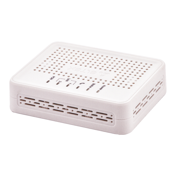
Fig. 5 shows NTU-2V side and top panels. Fig. 5—NTU-2V Top Panel The controls and LED indicators located on the NTU-2V side and top panels are shown in table . Table 4—Description of the LEDs and Controls Located on the Rear Panel... - Page 15 SC port (socket) for PON with GPON interface Fig. 7 shows a NTU-2V side and front panels. Fig. 7—NTU-2VC Top Panel The controls and LED indicators located on the NTU-2V side and top panels are shown in the table 6. ____________________________________________________________________________________ NTU Optical Network Terminals...
-
Page 16: Ntu-2W
____________________________________________________________________________________ Table 6 – Description of front panel LED indicators Panel Element Description Analogue phone indicator 1..2 Ethernet ports activity indicators CATV signal availability indicator Optical interface indicator Device authentication indicator Device power and activity status indicator 2.5.3 NTU-2W NTU-2W devices are designed as 147×110×24 mm desktop device in a plastic housing. The Fig. - Page 17 ____________________________________________________________________________________ Fig. 9—NTU-2W Top Panel The controls and LEDs located on the NTU-2W side and top panels are shown in the table 8. Table 8—Description of the LEDs and controls located on the side and top panels (replace the names with corresponding icons) Panel Element Description...
-
Page 18: Ntu-Rg-1402G-W
____________________________________________________________________________________ Table 9 – Description of the controls located on the bottom panel Bottom Panel Element Description a functional key that reboots the device and resets it to the factory settings 2.5.4 NTU-RG-1402G-W The NTU-RG-1402G-W subscriber terminal is designed as a desktop device in plastic housing. The Figure 10 shows the NTU-RG-1402G-W rear panel layout. -
Page 19: Light Indication
Reset settings Wi-Fi: Wi-Fi enabling/disabling button a button which enables automatic secure Wi-Fi connection 2.6 Light Indication 2.6.1 NTU-2V The LED indicators located on the front panel show the current state of the device. ____________________________________________________________________________________ NTU Optical Network Terminals... -
Page 20: Ntu-2Vc
____________________________________________________________________________________ Table 13 provides possible statuses of the LEDs. Table 13—Light Indication of Device Status LED Status Device Status device booting connection between optical line terminal and device is green established flashes green authentication failed at optical line terminal flashes red no signal from optical line terminal green established 10/100 Mbps connection... -
Page 21: Ntu-2W
____________________________________________________________________________________ is established flashes green authentication failed at optical line terminal flashes red no signal from optical line terminal WAN interface is in static or bridge mode, PPP client is not running green device was successfully authenticated on line terminal (PPP session started in WAN interface) orange device is not authenticated (PPP session is not started... -
Page 22: Ntu -Rg-1402G-W
7–10 seconds until the POWER indicator turns red. The factory settings have the following IP addresses: LAN—192.168.1.1, subnet mask—255.255.255.0. Access can be provided from LAN 1 and LAN 2 ports. 2.7 Delivery Package The NTU-2V(C), NTU-2W, NTU-RG standard delivery package includes: – NTU-2V, NTU-RG subscriber optical terminals; – 220V/12V power adapter; – Operation Manual. -
Page 23: Device Architecture
____________________________________________________________________________________ Device Architecture 3.1 NTU-2V(C) Architecture Fig. 12— Logical Architecture of a Device with Factory Settings Main Components of the Device: optical receiver/transmitter (SFF module) for conversion of an optical signal into an electric one; – – processor (PON chip) which converts Ethernet and GPON interfaces. - Page 24 ____________________________________________________________________________________ A connection to the OB device (successful connection to a stationary OLT) additionally creates the gpondef blocks with the help of the OMCI protocol (ONT Management and Control Interface). The block ensures connection of the subscriber’s ONT device to station-side equipment. Fig.
- Page 25 ____________________________________________________________________________________ veip0.1 is for the Internet; – veip0.2 controls the multicast traffic; – Veip0.3 provides VoIP services; – – veip0.6 provides VoD and IPTV on STB. These WAN interfaces have the following operation modes: – PPPoE—starts PPP client; – IPoE DHCP—starts DHCP client; IPoE Static—uses a static address;...
-
Page 26: Ntu-2W Architecture
____________________________________________________________________________________ 3.2 NTU-2W Architecture Fig. 15— Logical Architecture of a Device with Factory Settings Main Components of the Device: – optical receiver/transmitter (SFF module) for conversion of an optical signal into an electric one; processor (PON chip) which converts Ethernet and GPON interfaces. –... - Page 27 ____________________________________________________________________________________ Fig. 16—Architecture of the Device Configured for Triple Play Model 1 Services The blocks created by the OMCI protocol during connection to OLT (left) are shown for clarity and do not describe the real architecture. The gemport blocks represent logical terminals of gem ports that are used for transmitting traffic of various services.
- Page 28 ____________________________________________________________________________________ The bri blocks are the objects of the 2nd level and operate as bridges between the LAN and WAN interfaces to include the interface into one group. The br1 block is connected to the veip0.1 interface, which operates in the PPPoE mode, and to the eth0 port. The br2, br3 blocks operate as a bridge, which allows transparent traffic transmission to the LAN ports of the router.
-
Page 29: Ntu-Rg-1402G-W Architecture
____________________________________________________________________________________ 3.3 NTU-RG-1402G-W Architecture Fig. 18— Logical Architecture of a Device with Factory Settings Main Components of the Device: optical receiver/transmitter (SFF module) for conversion of an optical signal into an electric one; – processor (PON chip) which converts Ethernet and GPON interfaces. –... - Page 30 ____________________________________________________________________________________ The IPInterface block is a logical object with an IP address for LAN access and a DHCP server, which assigns addresses to clients. A connection to the OB device (successful connection to a stationary OLT) additionally creates the gpondef blocks with the help of the OMCI protocol (ONT Management and Control Interface). The block ensures connection of the subscriber’s ONT device to station-side equipment.
- Page 31 ____________________________________________________________________________________ The TR-069 client block is used for device remote control with the help of the ACS server (Auto Configuration Server) via TR-069 protocol. The block is used to establish communication between ACS and subscriber’s equipment, process ONT queries, and configure services. The WANConnectionDevice block is an object associated with WAN interface.
- Page 32 ____________________________________________________________________________________ Fig. 20—Architecture of the Device Configured for Triple Play Model 2 Services The difference between the models is the GEM4095 block, which is a logical terminal of the GEM port for broadcasting. It broadcasts traffic downstream. Broadcast packets are sent from the GEM4095 block to WAN Connection Device and then are further transmitted to bri according to VLAN ID.
-
Page 33: Ntu-Rg-1402G-W Configuration Via Web Interface. User Access
____________________________________________________________________________________ NTU-RG-1402G-W CONFIGURATION VIA WEB INTERFACE. USER ACCESS Device configuration requires accessing the device through a web browser (a program displaying hypertext documents) such as Firefox or Google Chrome. To do this, enter the device IP address into the address bar of the web browser (the factory default IP —192.168.1.1, subnet mask—255.255.255.0). -
Page 34: The Device Info Menu. Device Information
____________________________________________________________________________________ 4.1 The Device Info Menu. Device Information 4.1.1 The Summary Submenu. Device General Information – Board type—model of the device; – Serial number—serial number of the device; PON serial—serial number of the device in the PON network; – – Base WAN MAC—WAN MAC address of the device;... -
Page 35: The Detail Submenu. Detailed Information
4.1.3 The LAN Submenu. LAN Ports Monitoring. Wi-Fi Interface Status Monitoring Status and parameters of wired and wireless LAN interfaces are available in this menu. Status, data transfer rate, and mode (duplex/half-duplex) are shown for wired connections. NTU-2V(C) NTU-2W NTU-RG-1402G-W 4.1.4 The Statistics Submenu. - Page 36 ____________________________________________________________________________________ LAN interface: NTU-2V(C) NTU-2W NTU-RG-1402G-W WAN Service ____________________________________________________________________________________ NTU Optical Network Terminals...
-
Page 37: The Route Submenu. The Routing Table
____________________________________________________________________________________ Optical interface: If a device supports measurement of optical signal parameters , the menu displays an additional table: Link Status—optical link status; Optical Signal Level—level of the incoming signal (1490 nm); Transmit Optical Level—level of the outgoing signal (1310 nm); ... -
Page 38: The Arp Submenu. Arp Protocol Cache
____________________________________________________________________________________ – M—the route was changed by a redirected ICMP message; – Metric—priority of the route; – Service—corresponding service of the route; – Interface—corresponding network interface of the route. 4.1.6 The ARP Submenu. ARP Protocol Cache ARP performance heavily depends on the ARP cache, which is generated at every host. The cache contains Internet addresses and corresponding hardware addresses. -
Page 39: The Wireless Monitor Submenu. Detected Wi-Fi Networks
Click the Refresh button to refresh the data. 4.1.10 Voice submenu . Monitoring the phone port states Use the menu to view FXS port state and parameters of SIP accounts Only for NTU-2W, NTU-RG-1402G-W Only for NTU-2V(C), NTU-RG-1402G-W ____________________________________________________________________________________ NTU Optical Network Terminals... -
Page 40: The Advanced Setup Menu. Advanced Settings
____________________________________________________________________________________ – Voice daemon status – the status of voice daemon; – SIP Proxy – SIP Proxy address and port; – SIP Outbound Proxy – address and port of the SIP proxy which will be used to transfer all queries (this server will be used for routing of SIP Proxy and SIP Registrar queries);... -
Page 41: Pppoe Menu. Ppp1 Settings
____________________________________________________________________________________ 4.2.2 PPPoE menu. PPP1 Settings To enable the service, set the Enable Service flag. The Internet service has two available operation modes: IP_Routed – mode when PPPoE session starts on a subscriber device; PPPoE_Bridged – mode when PPPoE session starts on a user PC. —... -
Page 42: The Port Triggering Submenu. Port Triggering Configuration
____________________________________________________________________________________ – Use Interface— interface that is used; Available are only the interfaces configured to work in the router mode with enabled translation of network addresses. – Service Name—service settings: – Select a Service—select a preconfigured rule; – Custom Service—create new rules not listed in the Select a Service list; –... - Page 43 ____________________________________________________________________________________ To add rules to the table, click the Add button. Click Remove in front of a selected rule to remove it. – Use Interface— interface that is used. Available are only the interfaces configured to work in the router mode with enabled translation of network addresses.
-
Page 44: The Dmz Host Submenu. Dmz Settings
____________________________________________________________________________________ 4.2.3.3. The DMZ Host Submenu. DMZ Settings If the DMZ Host IP Address field contains an IP address, all requests from the external network that do not correspond the Virtual Server rules will be forwarded to the DMZ host (a trusted host with a specific address in LAN). - Page 45 ____________________________________________________________________________________ – Filter Name—text description of the filter; – IP Version—select IP protocol version; – Protocol—select protocol (TCP/UDP, TCP, UDP, ICMP); – MAC address—source MAC address; – Source IP address[/prefix length]—source IP address (the prefix length can be specified after a slash); –...
-
Page 46: The Mac Filtering Submenu. Filtering Settings For Mac Addresses
____________________________________________________________________________________ WAN (configured in the router mode and having a firewall enabled) and LAN Interfaces – Select All—when set, allows selection of all available interfaces. You can also select an interface from the list by setting a flag in front of it. Click the Apply/Save button to accept and save the settings. -
Page 47: The Parental Control Submenu. Parental Control-Restrictions Configuration
____________________________________________________________________________________ – WAN Interfaces (configured in the Bridge mode only)—select WAN interfaces from the drop-down list (only interfaces in the Bridge mode are available). To accept and save the settings, click the Apply/Save button. 4.2.5 The Parental Control Submenu. Parental Control—Restrictions Configuration 4.2.5.1. -
Page 48: The Dynamic Dns Menu. The Dynemic Dns Settings
____________________________________________________________________________________ – URL List Type—type of the URL list: – Exclude—denied addresses; – Include—allowed addresses; To add a new URL to a list, set the flag in front of the corresponding list (URL List Type) and click the Add button. –... - Page 49 ____________________________________________________________________________________ – D-DNS provider—select a type of the D-DNS service (provider): DynDNS.org, TZO.com, ZoneEdit.com, freedns.afraid.org, easyDNS.com, 3322.org, DynSIP.org, No-IP.com, dnsomatic.com, sitelutions.com; – Custom—any other provider selected by the user. In this case, the user will need to specify manually the provider's name and address: –...
-
Page 50: Print Server Menu. Print Server Configuration
____________________________________________________________________________________ – Username—user name for the DDNS account; – Password—password for the DDNS account; – DynDNS Type—select the type of the service registered at the provider: – Dynamic—Dynamic DNS service registered; – Static—Static DNS service registered; – Custom—Custom DNS service registered; –... -
Page 51: Voice Menu. Sip Settings
— SIP Outbound Proxy – SIP proxy address which will be used to transfer all requests (this server will be used for routing SIP Proxy and SIP Registrar); SIP settings are available for NTU-2V(C) and NTU-RG-1402G-W only. If this menu is absence in the configurator it means settings have already been completed by your service provider. -
Page 52: Sip Advanced Settings Submenu
____________________________________________________________________________________ — SIP Outbound Proxy port – SIP proxy port for transmitting all requests; — Use SIP Registrar – when checked, use SIP registrar server : — SIP Registrar – server address; — SIP Registrar port – server port; The table shows SIP parameters that are common for FXS ports. —... -
Page 53: The Wireless Menu. Wi-Fi Network Setup
____________________________________________________________________________________ — Call barring mode – call barring mode; — Call barring pin – password for outgoing calls; — Call barring digit map – digit map which allows/bars outgoing calls; — Warm line – when checked, ‘Warm Line’ service is enabled, otherwise the service is disabled. The service allows you to establish an outgoing connection automatically without dialing the number right after the lifting of a headset (‘hot line)’, or with delay (‘warm line’);... -
Page 54: The Security Submenu. Security Settings
SSID—Service Set Identifier—assign a name to the wireless network (case sensitive); The default name (SSID) of the wireless network is ELTEX-aaaa where aaaa are the last 4 digits of WAN MAC. WAN MAC is labelled on the device housing. The WAN MAC is labelled on the device housing. - Page 55 ____________________________________________________________________________________ These operations should be manually performed without WPS. To establish a connection, the user simply needs to press the WPS button located on the side panel of the device or use web configuration to enter a PIN code. WPS Setup –...
- Page 56 ____________________________________________________________________________________ AES—128-bit block encryption algorithm with 128/192/256-bit key, – generally used for WPA2; – WPA2-PSK—enables WPA2-PSK (the mode uses the WPA2 protocol but does not require the RADIUS authentication server); WPA/WAPI passphrase—secret phrase. Sets a password; a string of 8–63 ASCII characters.
-
Page 57: The Mac Filter Submenu. Mac Address Filtering Settings
____________________________________________________________________________________ The network key corresponds to the device serial number by default. The serial number is labelled on the device housing. When you change the password, you will need to specify a combination of 10 characters. The password must contain digits and Latin characters in upper and lower cases. -
Page 58: The Wireless Bridge Submenu. Configuration Of Wireless Connection In The Bridge Mode
____________________________________________________________________________________ Deny—filter by denied addresses. – To add a MAC address into the filter table, click the Add button and enter its value into the MAC address field in the displayed menu: Click the Apply/Save button to accept the changes. 4.4.4 The Wireless Bridge Submenu. - Page 59 ____________________________________________________________________________________ – Band—frequency coverage – Channel—select an operating channel for the router. Interference or any other issues of a wireless network may be solved by changing the channel. The parameter is recommended to be set to Auto to avoid interference caused by adjacent networks; –...
-
Page 60: Storage Service Menu. File Storage Service
____________________________________________________________________________________ – 802.11n Protection—when enabled, enhances the security, but decreases the bandwidth; – Support 802.11n Client Only – when enabled, denies 802.11b/g clients to access the device; – RIFS Advertisement—Reduced Interframe Space, reduces the interval between data units (PDUs), increases Wi-Fi efficiency; –... -
Page 61: User Accounts Submenu. Configuration Of Samba Users
____________________________________________________________________________________ Volumename – device name; – – FileSystem – file system type; – Total Space – total space; Used Space – used space; – – Unmount – a button for device safe disconnection or connection. 4.5.2 User Accounts submenu. Configuration of Samba users Use the menu to configure Samba accounts. -
Page 62: The Restore Default Submenu. Restore Default Settings
____________________________________________________________________________________ 4.6.1.3. The Restore Default Submenu. Restore Default Settings The menu restores the default settings. The device will be rebooted in this case. When operation is completed, all settings will be lost Click Restore Default Settings button to restore the default settings. When factory reset is completed the device will be automatically rebooted. -
Page 63: Ping Submenu. Checking The Availability Of The Network Devices
____________________________________________________________________________________ Time zone offset – set the time zone according to UTC. – Choosing the Other option in the drop-down list of servers activates a window to the right where the address of the time server can be manually entered. 4.6.4 Ping Submenu. -
Page 64: The View Submenu. System Log Display
____________________________________________________________________________________ – Log—enable/disable system log; – Log Level – sets the verbosity of the event log. Severity levels are in the descending order: – Emergency; – Alert; – Critical; – Error; – Warning; – Notice; – Informational; – Debugging; – Display Level—display level of the event log messages; –... -
Page 65: The Update Software Submenu. Software Update
____________________________________________________________________________________ Click Close to close the log display window. Use the Refresh button to refresh the information. 4.6.7 The Update Software Submenu. Software Update To update software, select the software in the Software File name field (use the Choose a File or Browse buttons) and click Update Software. -
Page 66: Appendix A. Possible Problems And Their Solutions
____________________________________________________________________________________ APPENDIX A. POSSIBLE PROBLEMS AND THEIR SOLUTIONS Problem Possible Cause Solution Web interface is not The computer is not in the Select the Obtain an IP address automatically available when the router same IP subnetwork for checkbox in the Internet connection settings on your IP address entered (e. -
Page 67: Appendix B. Additional Service
____________________________________________________________________________________ APPENDIX B. ADDITIONAL SERVICE 1. Call Waiting The service uses a definite signal to notify user about a new incoming call when the line is already busy with another call. Having received the signal, the user may decide to pick up the waiting call. The service can be chosen by setting Call waiting flag in the VoIP/SIP Advanced Setting menu (see section 4.3.2 SIP Advanced Settings submenu). - Page 68 ____________________________________________________________________________________ 4. Message Waiting Indication (MWI) If a voice message is left on the server for a subscriber, the service allows the subscriber to be timely notified about the message. When the MWI service is enabled and there is a new message on the server, the subscriber will hear a discontinuous buzzer when he picks up the phone.
-
Page 69: Ntu-2W Acceptance Certificate And Warranty
Equipment shipping and storage should be performed in accordance with GOST 15150 Conditions 5 and Conditions 1 respectively. The manufacturer, Eltex Ltd., guarantees that the subscriber gateway meets the requirements of technical specification TU6650-100-33433783-2013 provided its operation conditions correspond to the ones set forth in this Manual. -
Page 70: Ntu-2V Acceptance Certificate And Warranty
Equipment shipping and storage should be performed in accordance with GOST 15150 Conditions 5 and Conditions 1 respectively. The manufacturer, Eltex Ltd., guarantees that the subscriber gateway meets the requirements of technical specification TU6650-100-33433783-2013 provided its operation conditions correspond to the ones set forth in this Manual. -
Page 71: Ntu-2Vc Acceptance Certificate And Warranty
Equipment shipping and storage should be performed in accordance with GOST 15150 Conditions 5 and Conditions 1 respectively. The manufacturer, Eltex Ltd., guarantees that the subscriber gateway meets the requirements of technical specification TU6650-100-33433783-2013 provided its operation conditions correspond to the ones set forth in this Manual. -
Page 72: Ntu-2W Acceptance Certificate And Warranty
Equipment shipping and storage should be performed in accordance with GOST 15150 Conditions 5 and Conditions 1 respectively. The manufacturer, Eltex Ltd., guarantees that the subscriber gateway meets the requirements of technical specification TU6650-100-33433783-2013 provided its operation conditions correspond to the ones set forth in this Manual.
Need help?
Do you have a question about the NTU-2V and is the answer not in the manual?
Questions and answers