
Related Manuals for DSEGenset DSEA106


Summary of Contents for DSEGenset DSEA106
- Page 1 DEEP SEA ELECTRONICS DSEA106 MKII Operators Manual Document Number: 057-269 Author: Ashley Senior 057-269 ISSUE: 4...
- Page 2 Applications for the copyright holder’s written permission to reproduce any part of this publication must be addressed to Deep Sea Electronics Ltd. at the address above. The DSE logo and the names DSEGenset®, DSEAts®, DSEControl® and DSEPower® are UK registered trademarks of Deep Sea Electronics Ltd.
-
Page 3: Table Of Contents
DSEA106 MKII Operator Manual TABLE OF CONTENTS SECTION PAGE INTRODUCTION ....................5 CLARIFICATION OF NOTIFICATION ................. 5 GLOSSARY OF TERMS ..................... 6 BIBLIOGRAPHY ......................... 7 1.3.1 INSTALLATION INSTRUCTIONS ................. 7 1.3.2 MANUALS ........................7 1.3.3 TRAINING GUIDES ...................... 7 1.3.4 OTHER......................... - Page 4 DSEA106 MKII Operator Manual 4.4.1.3 UNDER FREQUENCY ROLL OFF (UFRO) PRESET ........... 33 4.4.2 ALTERNATE VOLTAGE RANGE ................34 4.4.3 ALTERNATE FREQUENCY RANGE ................34 4.4.4 ALTERNATE STABILITIES ..................34 4.4.5 PROTECTIONS ......................34 FINAL CHECK ........................35 OPERATION ...................... 36 CONTROLS AND INDICATIONS ..................
-
Page 5: Introduction
This document details the installation and operation requirements of the DSEA106 AVR and is part of the DSEGenset® range of products. The manual forms part of the product and should be kept for the entire life of the product. If the product is passed or supplied to another party, ensure that this document is passed to them for reference purposes. -
Page 6: Glossary Of Terms
Description DSEA000 All AVRs in the DSEAxxx range. DSEAxxx DSEA106 DSEA106 AVR Automatic Voltage Regulator An electronic device designed to automatically maintain a constant voltage output level of a generator. Current Transformer An electrical device that takes a large AC current and scales it down by a fixed ratio to a smaller current. -
Page 7: Bibliography
057-151 DSE Configuration Suite PC Software Installation & Operation Manual 057-271 DSEA106 MKII Configuration Suite PC Software Manual TRAINING GUIDES Training guides are provided as ‘hand-out’ sheets on specific subjects during training sessions and contain specific information regarding to that subject. -
Page 8: Specifications
0 V to 430 V and PD2 for 430 V to 600 V. For applications in Canada, the DSEA106 MKII is rated as PD3 for 0 V to 300 V and PD2 for 300 V to 600 V • Conductor protection must be provided in accordance with NFPA 70, Article 240 •... -
Page 9: Auxiliary Winding / Shunt Supply
Frequency Accuracy ±0.2 Hz. GENERATOR CURRENT MEASUREMENT The DSEA106 MKII measures current in a chosen phase for the purposes of quadrature droop using terminals S1 and S2. For further details, refer to the section entitled Quadrature Droop elsewhere in this document. -
Page 10: External Ac Voltage Bias
Specifications EXTERNAL AC VOLTAGE BIAS External voltage bias inputs are provided to allow an external circuit to influence the output of the generator. Parameter Description Potentiometer Bias Input 0 Ω to 5 kΩ (terminals P1 and P2) DC Voltage Bias Input Range -10 V to 10 V (terminals A1 and A2) DC Voltage Bias Input Impedance... -
Page 11: Output Power Limitation Curves
Specifications OUTPUT POWER LIMITATION CURVES Output Voltage vs Current Peak Conditions (Maximum 10 seconds) Continuous Conditions (Subject to maximum power output of 500 W) 10 11 12 13 14 15 16 Output Current (A) Exciter Power & Current vs Resistance Output Current (A) Output Power (W) Exciter Resistance (Ω) -
Page 12: Dimensions
Specifications DIMENSIONS Parameter Description Overall Size 179 mm x 108 mm x 61 mm (7.1 “ x 4.3 “ x 2.4 “) Mounting Type Screw Mounting to Chassis. Mounting Holes Suitable for M5 bolts/screws. Outside diameter 5.5 mm (Outside diameter 0.2 “) Mounting Hole Centres 149 mm x 85 mm (5.9 “... -
Page 13: Communication
COMMUNICATION NOTE: For further details of module configuration, refer to DSE Publication: 057-271 DSEA106 MKII Configuration Suite PC Software Manual. Caution: Do not disconnect the USB from DSE815 whilst it is connected to the AVR. Doing so results in loss of voltage control and potential damage to the generator. -
Page 14: Installation
Installation 3 INSTALLATION WARNING!: LIVE PARTS exist within the AVR. When powered avoid contact with components and terminals. To avoid damage to persons and/or property, only qualified personnel, having full understanding of the application must install the product. The AVR is designed to be mounted on the control panel chassis or within the alternator housing utilising the integral mounting holes. -
Page 15: Typical Wiring Diagrams
Installation TYPICAL WIRING DIAGRAMS NOTE: The DSEA106 MKII AVR is only suitable for alternators with Auxiliary Winding or Shunt connections. For alternators with Permanent Magnet Generator (PMG) connections, contact DSE Technical Support for more details: support@deepseaplc.com AUXILIARY WINDING CONNECTION WARNING!: LIVE PARTS exist within the AVR. When powered avoid contact with components and terminals. -
Page 16: Shunt Connection
Installation SHUNT CONNECTION WARNING!: LIVE PARTS exist within the AVR. When powered avoid contact with components and terminals. To avoid damage to persons and/or property, only qualified personnel, having full understanding of the application must install the product. 057-269 ISSUE: 4 Page 16 of 48... -
Page 17: Alternate Topology Wiring Diagrams
Installation ALTERNATE TOPOLOGY WIRING DIAGRAMS Page 17 of 48 057-269 ISSUE: 4... -
Page 18: Setup Procedure
Doing so results in loss of voltage control and potential damage to the generator. NOTE: For further details of module configuration, refer to DSE Publication: 057-271 DSEA106 MKII Configuration Suite PC Software Manual. The engine must be commissioned as far as possible before this procedure is carried out, in particular the governor must be setup to produce stable speed control at 1500 RPM / 1800 RPM. - Page 19 Setup Procedure Using DSE Configuration Suite PC Software, select the 90 V to 300 V appropriate voltage menu Low Voltage Range (for 90 V to 300 V systems) or High Voltage Range (for 180 V to 600 V systems). This voltage refers to the voltage applied to the AVR L and N (L2) terminals (the sensing voltage).
- Page 20 Setup Procedure Open the selected Stability Configuration page. Preset Enable Ensure the Proportional and Integral Preset remains ‘checked’ Enable options are checked, and set the Preset Range of both to 100 %. Preset Enable remains ‘checked’ Set the Derivative Set Point to 0. Set the Maximum Duty Cycle to 100 %.
- Page 21 Setup Procedure Using DSE Configuration Suite PC Software, connect SCADA and select the Commissioning Screen display. Set the Proportional preset on the AVR to approximately 10. Set the Integral preset on the AVR between 1 and 2. Ensure the derivative value is 0, and the Output Duty Cycle is 100 % with the engine not running.
-
Page 22: First Start
NOTE: Do not apply load to the set until instructed during the following procedure. NOTE: For further details of module configuration, refer to DSE Publication: 057-271 DSEA106 MKII Configuration Suite PC Software Manual. Start the generating set and observe the feedback voltage using the SCADA screen and the voltmeter. -
Page 23: Low Output Voltage After First Start
NOTE: For further details of module configuration, refer to DSE Publication: 057-271 DSEA106 MKII Configuration Suite PC Software Manual. OFF LOAD DUTY CYCLE SETTING With the set running off load, take note... -
Page 24: Proportional
Setup Procedure The following subsections details the procedure for calibrating the Proportional, Integral, and Derivative settings for optimal generator load acceptance and operation. Wherever possible, a load bank is to be used to ensure stable voltage control during different loading conditions. If a load bank is not available, the Voltage Set Point Step function is used to emulate load step changes. -
Page 25: Derivative
Setup Procedure 4.1.1.3 DERIVATIVE NOTE: Proceed below only after setting both Proportional and Integral. NOTE: If an oscilloscope is not available, the voltmeter and SCADA screen are used solely. This does not show rapid oscillation of the voltage output and hence does not provide the optimum setup environment. - Page 26 Setup Procedure The AVR’s response to these Voltage Set Point Step changes indicate how well the current stability settings handle load changes, and what further adjustments may be required. Example oscilloscope traces of the AVR’s ‘transient response’ to Voltage Set Point Step changes are shown below: Voltage Set Point Steady State...
-
Page 27: Soft Start Ramp
Setup Procedure 4.1.1.5 SOFT START RAMP Once the stability settings have been completed, the Soft Start Ramp values can be set. The Ramp Start Point value determines the percentage of the configured voltage Set Point at which the Soft Start Ramp takes effect. If a voltage spike at a value below the voltage Set Point is shown on start up, decrease this value. -
Page 28: Droop Setting
Setup Procedure DROOP SETTING NOTE: Proceed with Droop setting only after the AVR has been correctly stabilised by following the Stability Settings section first. Quadrature Droop monitors the reactive power provided by the generator to the load and is used to provide kvar sharing (reactive load sharing) between generators. -
Page 29: Obtaining And Configuring Ct Phase Shift
Setup Procedure 4.1.1.7 OBTAINING AND CONFIGURING CT PHASE SHIFT NOTE: It is very important that Droop Initial Setup procedure is followed before continuing. To account for the choices made for the CT, its location and which phases are used for voltage sensing, Offset Angle must be configured correctly. -
Page 30: External Bias Setting
Setup Procedure EXTERNAL BIAS SETTING NOTE: Proceed with External Bias Setting only after the AVR has been correctly stabilised by following the Stability Settings section first. 4.1.1.9 EXTERNAL POTENTIOMETER NOTE: The external potentiometer is designed for manual adjustment of the output voltage. -
Page 31: Dc Voltage Input
Setup Procedure 4.1.1.10 DC VOLTAGE INPUT NOTE: The DC Voltage Input is designed for automatic voltage matching or kvar sharing. For manual adjustment, use the External Potentiometer input instead. NOTE: Where both (External Potentiometer and DC Voltage Input) are used simultaneously, both inputs are summed to determine the output voltage. -
Page 32: Finalising Setup
Setup Procedure FINALISING SETUP NOTE: For further details of module configuration, refer to DSE Publication: 057-271 DSEA106 MKII Configuration Suite PC Software Manual. PRESETS WARNING!: Use only a suitable insulated potentiometer (preset) adjustment tool. Presets are the adjusters fitted on the AVR and may be disabled if end user adjustment is not required. -
Page 33: Voltage Preset
Setup Procedure 4.1.1.11 VOLTAGE PRESET If the voltage preset is required to be active, check the Preset Enable parameter in the configuration and set the Anticlockwise Limit of Preset and Clockwise Limit of Preset to give the desired control span. Write the configuration to the AVR. -
Page 34: Alternate Voltage Range
ALTERNATE FREQUENCY RANGE NOTE: The Alternate Frequency Range DIP switch is not functional when the Auto Frequency Detection function is enabled. For further details of module configuration, refer to DSE Publication: 057-271 DSEA106 MKII Configuration Suite PC Software Manual. DIP Switch Function... -
Page 35: Final Check
Setup Procedure FINAL CHECK Start the generator set and check that it reaches the set voltage and is stable. Test with various step loads within the limits of the generator and check that the voltage is stable with good transient response. Increase to full load and check that the alternator output remains at the set voltage and is stable. -
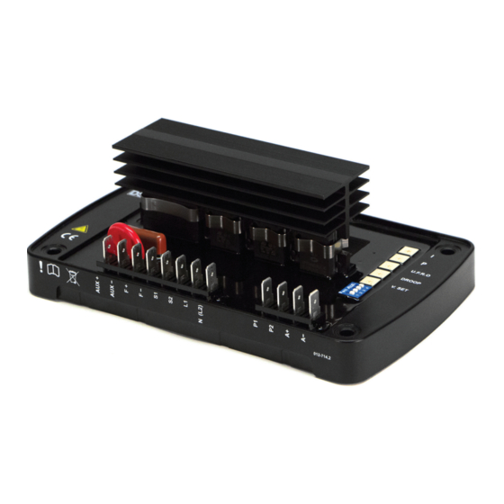
Page 36: Operation
Operation 5 OPERATION NOTE: For further details of module configuration, refer to DSE Publication: 057-271 DSEA106 MKII Configuration Suite PC Software Manual. CONTROLS AND INDICATIONS Status LED DIP Switch 1 to 4 Location of Presets Voltage Set Point Droop U.F.R.O. -
Page 37: Presets
Operation PRESETS It is possible to disable the operation of the preset using DSE Configuration Suite PC Software in conjunction with DSE815 Interface. In this instance, the value of the disabled preset is fixed by the PC Software. 5.1.1.1 VOLTAGE SET POINT The Setting for the alternators output voltage. - Page 38 Operation Multiple Generators In a multiple generator system, the droop on the AVR is working to minimise the alternators kvar production. If the droop on each AVR is set identically, it balances the kvars between all the alternators as they each try to produce the minimum reactive power. This enables a basic form of reactive power (kvar) sharing between connected generators, providing each AVR is configured to provide the same amount of droop.
-
Page 39: Under Frequency Roll Off (Ufro)
UNDER FREQUENCY ROLL OFF (UFRO) NOTE: For further details of module configuration, refer to DSE Publication: 057-271 DSEA106 MKII Configuration Suite PC Software Manual. To help protect the alternator, output excitation is limited when generator output frequency is low, this is known as Under Frequency Roll Off. -
Page 40: Proportional
Adjusts the Proportional gain of the AVR output control. Turning the preset clockwise raises the Proportional gain. Should the generator output be different from the DSEA106 MKII Voltage Set Point, a jump in Excitation Output is made to correct the error. The amplitude of this jump is governed by the Proportional Gain. -
Page 41: Dip Switch Adjustment
Operation DIP SWITCH ADJUSTMENT DIP switches are used to select the operating range of the A.V.R. Switch locations are shown in the section entitled Controls and Indications elsewhere in this document. DIP Switch 1 to 4 DIP Switch 1 and 2 Functionality DIP Switch Function Voltage Sensing Range... -
Page 42: Status Led
Operation STATUS LED An LED shows operating status of the A.V.R. LED state Cause Possible Solution Running, or stationary but powered by U.S.B. Rapid Continuous Corrupt configuration Write the configuration to the AVR again, if this Flashing reoccurs the AVR is faulty and should be returned. Single Flash Start-up Failed Trip Delayed by 10 seconds if the setup instructions were... -
Page 43: External Ac Voltage Bias
EXTERNAL AC VOLTAGE BIAS NOTE: Voltage adjust range is configured using DSE Configuration Suite PC Software. For further details, refer to DSE Publication: 057-271 DSEA106 MKII Configuration Suite PC Software Manual. Two external bias inputs are provided to allow remote adjustment of the alternator output. -
Page 44: Alarms
LOSS OF FEEDBACK NOTE: Loss of Feedback Delay is configured using DSE Configuration Suite PC Software. For further details, refer to DSE Publication: 057-271 DSEA106 MKII Configuration Suite PC Software Manual. During normal running operation the main generator output is monitored. If this drops below 5% of the Voltage Set Point for the duration of the Loss of Feedback Delay time, the Loss of Feedback alarm occurs. -
Page 45: Fault Diagnosis
Fault Diagnosis 7 FAULT DIAGNOSIS Nature of Problem Suggestion The Status LED is flashing. See section entitled Status LED elsewhere in this document. The Status LED is not lit. The generator may be stopped and the communication lead (DSE815 interface is not connected). See section entitled Status LED elsewhere in this document. -
Page 46: Maintenance, Spares, Repair And Servicing
Maintenance, Spares, Repair and Servicing 8 MAINTENANCE, SPARES, REPAIR AND SERVICING The module is designed to be Fit and Forget. As such, there are no user serviceable parts. In the case of malfunction you should contact your original equipment supplier (OEM). Connection Description Part No. - Page 47 This Page is Intentionally Blank...
- Page 48 This Page is Intentionally Blank...
Need help?
Do you have a question about the DSEA106 and is the answer not in the manual?
Questions and answers