
Related Manuals for DSEGenset DSEA108


Summary of Contents for DSEGenset DSEA108
- Page 1 DEEP SEA ELECTRONICS PLC DSEA108 Operator Manual Document Number: 057-281 Author: Jack Zochling ISSUE: 1...
- Page 2 DSEA108 Operator Manual Deep Sea Electronics Plc Highfield House Hunmanby North Yorkshire YO14 0PH ENGLAND Sales Tel: +44 (0) 1723 890099 Sales Fax: +44 (0) 1723 893303 E-mail: sales@deepseaplc.com Website: www.deepseaplc.com DSEA108 Operator Manual © Deep Sea Electronics Plc All rights reserved. No part of this publication may be reproduced in any material form (including...
-
Page 3: Table Of Contents
DSEA108 Operator Manual Table of Contents SECTION PAGE INTRODUCTION ....................5 CLARIFICATION OF NOTIFICATION ..................5 GLOSSARY OF TERMS ......................5 BIBLIOGRAPHY ........................6 SPECIFICATIONS ....................7 REQUIREMENTS FOR UL CERTIFICATION ................. 7 TERMINAL SPECIFICATION ....................7 AUXILIARY WINDING / SHUNT SUPPLY ................8 GENERATOR VOLTAGE AND FREQUENCY SENSING ............ - Page 4 DSEA108 Operator Manual 4.4.3 ALTERNATE FREQUENCY RANGE ................33 4.4.4 ALTERNATE STABILITIES ..................... 33 4.4.5 PROTECTIONS....................... 33 FINAL CHECK ........................34 OPERATION ...................... 35 CONTROLS AND INDICATIONS ..................35 5.1.1 PRESETS ........................36 5.1.1.1 VOLTAGE SET POINT .................... 36 5.1.1.2 DROOP ........................
-
Page 5: Introduction
This is not a controlled document. You will not be automatically informed of updates. Any future updates of this document will be included on the DSE website at www.deepseaplc.com For details on configuring the DSEA108 using a PC, refer to the relevant configuration software manual. -
Page 6: Bibliography
053-233 DSEA108 Installation Instructions 1.3.2 MANUALS DSE Part Description 057-238 DSEA108 Configuration Suite PC Software Manual 1.3.3 THIRD PARTY DOCUMENTS The following third party documents are also referred to: Reference Description IEEE Std C37.2-1996 IEEE Standard Electrical Power System Device ISBN 1-55937-879-4 Function Numbers and Contact Designations. -
Page 7: Specifications
0 V to 430 V and PD2 for 430 V to 600 V. For applications in Canada, the DSEA108 is rated as PD3 for 0 V to 300 V and PD2 for 300 V to 600 V • Conductor protection must be provided in accordance with NFPA 70, Article •... -
Page 8: Auxiliary Winding / Shunt Supply
Frequency Accuracy ±0.2 Hz. 2.5 GENERATOR CURRENT MEASUREMENT The DSEA108 measures current in a chosen phase for the purposes of quadrature droop using terminals S1 and S2. For further details, refer to the section entitled Quadrature Droop elsewhere in this document. -
Page 9: External Voltage Bias
Specifications 2.6 EXTERNAL VOLTAGE BIAS External voltage bias inputs allow an external circuit to influence the output of the generator. Parameter Description Potentiometer Bias Input 0 Ω to 5 kΩ (terminals P1 and P2) DC Voltage Bias Input Range -10 V to 10 V (terminals A1 and A2) DC Voltage Bias Input Impedance >... -
Page 10: Output Power Limitation Curves
Specifications 2.8 OUTPUT POWER LIMITATION CURVES Output Voltage vs Current Peak Conditions (Maximum 10 seconds) Continuous Conditions (Subject to maximum power output of 500 W) 10 11 12 13 14 15 16 Output Current (A) Exciter Power & Current vs Resistance Output Current (A) Output Power (W) Exciter Resistance (Ω) -
Page 11: Dimensions
Specifications 2.9 DIMENSIONS Parameter Description Overall Size 179 mm x 108 mm x 61 mm (7.1 “ x 4.3 “ x 2.4 “) Mounting Type Screw Mounting to Chassis. Mounting Holes Suitable for M5 bolts/screws. Outside diameter 5.5 mm (Outside diameter 0.2 “) Mounting Hole Centres 149 mm x 85 mm (5.9 “... -
Page 12: Communications
2.11.2 CONFIGURATION PORT NOTE: For further details of module configuration, refer to DSE Publication: 057-283 DSEA108 Configuration Suite PC Software Manual. In conjunction with the DSE815 Configuration Interface, the Configuration Port is provided to give a simple means of connection between a PC and the controller. -
Page 13: Installation
The DSEA108 is designed to be mounted on the control panel chassis or within the alternator housing utilising the integral mounting holes. For dimension and mounting details, see the section entitled Specifications, Dimensions elsewhere in this document. -
Page 14: Typical Wiring Diagrams
NOTE: The DSEA108 AVR is only suitable for alternators with Auxiliary Winding or Shunt connections. For alternators with Permanent Magnet Generator (PMG) connections, contact DSE Technical Support for more details: support@deepseaplc.com... -
Page 15: Auxiliary Winding Connection
Installation 3.2.1 AUXILIARY WINDING CONNECTION Page 15 of 58 057-281 ISSUE: 1... -
Page 16: Shunt Connection
Installation 3.2.2 SHUNT CONNECTION 057-281 ISSUE: 1 Page 16 of 58... -
Page 17: Setup Procedure
NOTE: For further details of module configuration, refer to DSE Publication: 057-271 DSEA108 Configuration Suite PC Software Manual. The engine must be commissioned as far as possible before this procedure is carried out, in particular the governor must be setup to produce stable speed control at 1500 RPM / 1800 RPM. - Page 18 Setup Procedure Using DSE Configuration Suite PC Software, select the appropriate Voltage Set Point. The Low Voltage Range (for 90 V to 300 V systems) or High Voltage Range (for 180 V to 600 V systems). This voltage refers to the voltage applied to the AVR L and N (L2) terminals (the sensing voltage).
- Page 19 Setup Procedure Open the selected Stability Configuration page. Ensure the Proportional and Integral Preset Enable options are checked, and set the Preset Range of both Preset Enable to 100 %. remains ‘checked’ Preset Enable remains ‘checked’ Set the Derivative Set Point to 0. Set the Maximum Duty Cycle to 100 %.
- Page 20 Setup Procedure Using DSE Configuration Suite PC Software, connect SCADA and select the Commissioning Screen display. Set the Proportional preset on the AVR to approximately 10. Set the Integral preset on the AVR between 1 and 2. Ensure the derivative value is 0, and the Output Duty Cycle is 100 % with the engine not running.
-
Page 21: First Start
NOTE: Do not apply load to the set until instructed during the following procedure. NOTE: For further details of module configuration, refer to DSE Publication: 057-271 DSEA108 Configuration Suite PC Software Manual. Start the generating set and observe the feedback voltage using the SCADA screen and the voltmeter. -
Page 22: Low Output Voltage After First Start
NOTE: For further details of module configuration, refer to DSE Publication: 057-271 DSEA108 Configuration Suite PC Software Manual. 4.3.1 OFF LOAD DUTY CYCLE SETTING With the set running off load, take note... -
Page 23: Stability Settings
Setup Procedure 4.3.2 STABILITY SETTINGS The following subsections detail the procedure for setting up the Proportional, Integral, and Derivative stability settings for optimal AVR load acceptance and operation. 4.3.2.1 PROPORTIONAL NOTE: If an oscilloscope is not available, the voltmeter and SCADA screen are used solely. -
Page 24: Voltage Set Point Step
Setup Procedure 4.3.2.3 VOLTAGE SET POINT STEP The Voltage Set Point Step feature allows the configured stability settings to be tested, without the use of a load bank. The voltage Set Point is increased and decreased by a pre- defined percentage, at the set interval for a set number of cycles. -
Page 25: Derivative
Setup Procedure 4.3.2.4 DERIVATIVE NOTE: Proceed below only after setting both Proportional and Integral. NOTE: If an oscilloscope is not available, the voltmeter and SCADA screen are used solely. This does not show rapid oscillation of the voltage output and hence does not provide the optimum setup environment. -
Page 26: Soft Start Ramp
Setup Procedure 4.3.2.5 SOFT START RAMP Once the stability settings have been completed, the Soft Start Ramp values can be set. The Ramp Start Point value determines the percentage of the configured voltage Set Point at which the Soft Start Ramp takes effect. If a voltage spike at a value below the voltage Set Point is shown on start up, decrease this value. -
Page 27: Droop Setting
Setup Procedure 4.3.3 DROOP SETTING NOTE: Proceed with Droop setting only after the AVR has been correctly stabilised by following the Stability Settings section first. Quadrature Droop monitors the reactive power provided by the generator to the load and is used to provide kvar sharing (reactive load sharing) between generators. -
Page 28: Pre-Defined Droop Setup
Setup Procedure 4.3.3.2 PRE-DEFINED DROOP SETUP NOTE: When completing a pre-defined droop setup, the DSEA108 must be wired as shown to match the selected topology in Configuration Suite. Failure to do so causes erroneous droop operation. The pre-defined droop setup procedure is... -
Page 29: Obtaining And Configuring Ct Phase Shift
Setup Procedure 4.3.3.3 OBTAINING AND CONFIGURING CT PHASE SHIFT NOTE: It is very important that Droop Initial Setup procedure is followed before continuing. To account for the choices made for the CT, its location and which phases are used for voltage sensing, Offset Angle must be configured correctly. -
Page 30: Dc Voltage Input
Setup Procedure 4.3.4.2 DC VOLTAGE INPUT NOTE: The DC Voltage Input is designed for automatic voltage matching or kvar sharing. For manual adjustment, use the External Potentiometer input instead. NOTE: Where both (External Potentiometer and DC Voltage Input) are used simultaneously, both inputs are summed to determine the output voltage. -
Page 31: Finalising Setup
Setup Procedure 4.4 FINALISING SETUP NOTE: For further details of module configuration, refer to DSE Publication: 057-271 DSEA108 Configuration Suite PC Software Manual. 4.4.1 PRESETS WARNING!: Use only a suitable insulated potentiometer (preset) adjustment tool. Presets are the adjusters fitted on the AVR and may be disabled if end user adjustment is not required. -
Page 32: Voltage Preset
Setup Procedure 4.4.1.1 VOLTAGE PRESET If the voltage preset is required to be active, check the Preset Enable parameter in the configuration and set the Anticlockwise Limit of Preset and Clockwise Limit of Preset to give the desired control span. Write the configuration to the AVR. -
Page 33: Alternate Voltage Range
4.4.3 ALTERNATE FREQUENCY RANGE NOTE: The Alternate Frequency Range DIP switch is not functional when the Auto Frequency Detection function is enabled. For further details of module configuration, refer to DSE Publication: 057-271 DSEA108 Configuration Suite PC Software Manual. DIP Switch Function... -
Page 34: Final Check
Setup Procedure 4.5 FINAL CHECK Start the generator set and check that it reaches the set voltage and is stable. Test with various step loads within the limits of the generator and check that the voltage is stable with good transient response. Increase to full load and check that the alternator output remains at the Set Point and is stable. -
Page 35: Operation
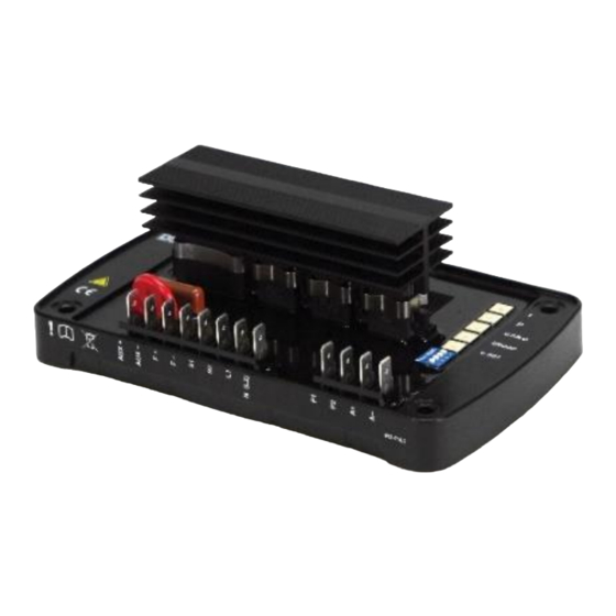
Operation 5 OPERATION NOTE: For further details of module configuration, refer to DSE Publication: 057-271 DSEA108 Configuration Suite PC Software Manual. 5.1 CONTROLS AND INDICATIONS Status LED DIP Switch 1-4 Location of Presets Voltage Set Point Droop U.F.R.O. Proportional Integral... -
Page 36: Presets
Operation 5.1.1 PRESETS It is possible to disable the operation of the preset using DSE Configuration Suite PC Software in conjunction with DSE815 Interface. In this instance, the value of the disabled preset is fixed by the PC Software. 5.1.1.1 VOLTAGE SET POINT The Setting for the alternators output voltage. - Page 37 Operation Multiple Generators In a multiple generator system, the droop on the AVR is working to minimise the alternators kvar production. If the droop on each AVR is set identically, it balances the kvars between all the alternators as they each try to produce the minimum reactive power. This enables a basic form of reactive power (kvar) sharing between connected generators, providing each AVR is configured to provide the same amount of droop.
-
Page 38: Under Frequency Roll Off (Ufro)
UNDER FREQUENCY ROLL OFF (UFRO) NOTE: For further details of module configuration, refer to DSE Publication: 057-271 DSEA108 Configuration Suite PC Software Manual. To help protect the alternator, output excitation is limited when generator output frequency is low, this is known as Under Frequency Roll Off. This reduces the alternator output voltage which in turn, reduces the load on the generator. -
Page 39: Proportional
Adjusts the Proportional gain of the AVR output control. Turning the preset clockwise raises the Proportional gain. Should the generator output be different from the DSEA108 Voltage Set Point, a jump in Excitation Output is made to correct the error. The amplitude of this jump is governed by the Proportional Gain. -
Page 40: Dip Switches
Operation 5.1.2 DIP SWITCHES DIP switches are used to select between different configurations within the device. Each configuration is adjusted using DSE Configuration Suite PC Software. DIP Switch 1-4 5.1.2.1 DIP SWITCH 1 Function DIP Switch 1 Stability Configuration 1 Stability Configuration 2 5.1.2.2 DIP SWITCH 2 AND 3... -
Page 41: Status Led
Operation 5.2.1 STATUS LED An LED shows operating status of the A.V.R. LED state Cause Possible Solution Running, or stationary but powered by U.S.B. Rapid Continuous Corrupt configuration Write the configuration to the AVR again, if this Flashing reoccurs the AVR is faulty and should be returned. Single Flash Start-up Failed Trip Delayed by 10 seconds if the setup instructions... -
Page 42: External Ac Voltage Bias
5.3 EXTERNAL AC VOLTAGE BIAS NOTE: Voltage adjust range is configured using DSE Configuration Suite PC Software. For further details, refer to DSE Publication: 057-271 DSEA108 Configuration Suite PC Software Manual. Two external bias inputs are provided to allow remote adjustment of the alternator output. -
Page 43: Alarms
6.2 LOSS OF FEEDBACK NOTE: Loss of Feedback Delay is configured using DSE Configuration Suite PC Software. For further details, refer to DSE Publication: 057-271 DSEA108 Configuration Suite PC Software Manual. During normal running operation the main generator output is monitored. If this drops below 5% of the Voltage Set Point for the duration of the Loss of Feedback Delay time, the Loss of Feedback alarm occurs. -
Page 44: Fault Diagnosis
Fault Diagnosis 7 FAULT DIAGNOSIS Nature of Problem Suggestion The Status LED is flashing. See section entitled Status LED elsewhere in this document. The Status LED is not lit. The generator may be stopped and the communication lead (DSE815 interface is not connected). See section entitled Status LED elsewhere in this document. -
Page 45: Can Interface Specification
CAN Interface Specification 8 CAN INTERFACE SPECIFICATION In addition to the Configuration port, the DSEA108 features a CAN communication port. The CAN port is used for live operational communications between the DSEA108 and compatible DSE genset controllers, encompassing both the transmission of AVR data and the receipt of external commands where applicable. -
Page 46: Vrep - Voltage Regulator Excitation Status
CAN Interface Specification VREP – VOLTAGE REGULATOR EXCITATION STATUS 8.1.1.1 Priority Ext Data Page Data Page PDU Format PDU Specific Size (Bytes) Rate 100 ms Decimal Instrument Byte / Bit Scaling Offset Units 0D34 3380 Generator Excitation Field Voltage Byte 1 to 2 0.05 V/bit - 1606.0 V 0D35... -
Page 47: Dm1 (Diagnostic Message 1)
CAN Interface Specification 8.1.1.4 DM1 (DIAGNOSTIC MESSAGE 1) Priority Ext Data Page Data Page PDU Format PDU Specific Size (Bytes) Rate 100 ms An alarm resulting in the shutdown of AVR excitation sets the DM1 Red Stop Lamp bits. The only exception to this is the Under Frequency alarm as this condition occurs during a normal generator stop sequence. -
Page 48: Propb 03 - Avr Status And Version
CAN Interface Specification PROPB 03 – AVR STATUS AND VERSION 8.1.1.7 Priority Ext Data Page Data Page PDU Format PDU Specific Size (Bytes) Rate Decimal Instrument Byte / Bit Scaling Offset Units 7F00C 520204 Software Version Major Byte 1 7F00D 520205 Software Version Minor Byte 2... -
Page 49: Propb 32 - Configurable Can Message 1
8.1.1.9 NOTE: The Values in Configurable CAN Message 1 are selected using DSE Configuration Suite PC Software. For further details of module configuration, refer to DSE Publication: 057- 283 DSEA108 Configuration Suite PC Software Manual. Priority Ext Data Page Data Page... -
Page 50: Received Messages
0xFFFF (Decimal 65535). 8.1.3 ALTERNATIVE CONFIGURATION Where enabled in the DSEA108 Configuration, this allows the default configuration to be selected. Selecting a disabled configuration or attempting to select a configuration when this feature is disabled results in the DSEA108 continuing to use the previously selected configuration. -
Page 51: Configuration
NOTE: To differentiate between the instrumentation/control and configuration, all configuration commands in the following subsections use Data Page 1. DSEA108 additionally supports configuration changes using the following CAN commands. DSEA108 also confirms receipt of the configuration commands. 8.2.1 MESSAGE FORMAT... -
Page 52: Read Command
Value (32 bit) Error Code 8.2.2.3 STORE CONFIGURATION COMMAND This command is used to instruct the DSEA108 to store the configuration in Non-Volatile Memory. This ensures all changed values are retained should the DSEA108 be powered down. Byte1 Byte2 Byte3... -
Page 53: Error Codes
CAN Interface Specification 8.2.3 ERROR CODES Error code Description No Error Invalid Address Attempting to Write to a Value That is ‘Read Only’. Value Out of Range Failed to Write 8.2.4 DATA ADDRESSES R/W: Read/Write R: Read Only Address Description Range Type Scaling and units... -
Page 54: Status Flag List
CAN Interface Specification Data Addresses Continued. R/W: Read/Write R: Read Only Index Description Range Type Scaling and units Output limit overshoot 0 to 300 Output limit overshoot delay 0 to 100 0.1 s Soft Start Ramp Start Point (%) 100 to 900 0.1 % Soft Start Ramp Rate (% / Hz) 50 to 1000... -
Page 55: Dip Switch Position List
CAN Interface Specification 8.2.4.2 DIP SWITCH POSITION LIST DIP Switch Positions (Address 208) are described as follows: Description Switch 1 (Stability selection) Switch 2 (Alternative Configuration Selection) Switch 3 (Alternative Configuration Selection) Switch 4 (Alternative Configuration Selection) 8 to 31 Not Used (all bits set to 1) Where the status is shown by the following bit patterns: Value (binary) -
Page 56: Maintenance, Spares, Repair And Servicing
Maintenance, Spares, Repair and Servicing 9 MAINTENANCE, SPARES, REPAIR AND SERVICING The module is designed to be Fit and Forget. As such, there are no user serviceable parts. In the case of malfunction, you should contact your original equipment supplier (OEM). Connection Description Part No. - Page 57 This Page is Intentionally Blank...
- Page 58 This Page is Intentionally Blank...
Need help?
Do you have a question about the DSEA108 and is the answer not in the manual?
Questions and answers