
Subscribe to Our Youtube Channel
Related Manuals for DSEGenset DSE6010 MKII


Summary of Contents for DSEGenset DSE6010 MKII
- Page 1 DEEP SEA ELECTRONICS PLC DSE6010 MKII & DSE6020 MKII Operator Manual Document Number: 057-230 Author: Mark Graham 057-230 IS 057-230 ISSUE: 1...
- Page 2 Sales Fax: +44 (0) 1723 893303 E-mail: sales@deepseaplc.com Website: www.deepseaplc.com DSE6010 MKII & DSE6020 MKII Operator Manual © Deep Sea Electronics Plc All rights reserved. No part of this publication may be reproduced in any material form (including photocopying or storing in any medium by electronic means or other) without the written permission of the copyright holder except in accordance with the provisions of the Copyright, Designs and Patents Act 1988.
-
Page 3: Table Of Contents
TABLE OF CONTENTS Section Page INTRODUCTION ....................7 BIBLIOGRAPHY ........................8 1.1.1 INSTALLATION INSTRUCTIONS .................8 1.1.2 TRAINING GUIDES .......................8 1.1.3 MANUALS ........................8 1.1.4 THIRD PARTY DOCUMENTS ..................8 SPECIFICATION ....................9 SHORT NAMES ........................9 OPERATING TEMPERATURE ....................9 2.2.1 SCREEN HEATER OPERATION ..................9 REQUIREMENTS FOR UL CERTIFICATION ..............9 TERMINAL SPECIFICATION.....................10 POWER SUPPLY REQUIREMENTS .................10... - Page 4 CONFIGURABLE DIGITAL INPUTS ................32 3.1.6 PC CONFIGURATION INTERFACE CONNECTOR ..........33 TYPICAL WIRING DIAGRAM ....................34 3.2.1 DSE6010 MKII TYPICAL WIRING DIAGRAM (3 PHASE 4 WIRE) ......35 3.2.2 DSE6020 MKII TYPICAL WIRING DIAGRAM (3 PHASE 4 WIRE) ......36 ALTERNATE TOPOLOGY WIRING DIAGRAMS ..............37 3.3.1 GENERATOR ......................37...
- Page 5 5.5.3 ENGINE RUNNING .....................71 5.5.4 STOPPING SEQUENCE .....................71 MAINTENANCE ALARM ....................72 SCHEDULER........................73 5.7.1 STOP MODE .......................73 5.7.2 MANUAL MODE ......................73 5.7.3 TEST MODE ........................73 5.7.4 AUTO MODE .......................73 FRONT PANEL CONFIGURATION ............... 74 ACCESSING THE FRONT PANEL CONFIGURATION EDITOR ........75 ADJUSTABLE PARAMETERS ..................76 6.2.1 MODULE SETTINGS ....................76...
- Page 6 11.1 WEEE (WASTE ELECTRICAL AND ELECTRONIC EQUIPMENT) ......98 057-230 ISSUE: 1 Page 6 of 100...
-
Page 7: Introduction
Introduction 1 INTRODUCTION This document details the installation and operation requirements of the DSE6010 MKII & DSE6020 MKII modules, part of the DSEGenset® range of products. The manual forms part of the product and should be kept for the entire life of the product. If the product is passed or supplied to another party, ensure that this document is passed to them for reference purposes. -
Page 8: Bibliography
Product manuals are can be downloaded from the DSE website: www.deepseaplc.com DSE Part Description 057-004 Electronic Engines and DSE Wiring Guide 057-223 DSE6010 MKII & DSE6020 MKII Configuration Suite PC Software Manual THIRD PARTY DOCUMENTS 1.1.4 The following third party documents are also referred to: Reference Description IEEE Std C37.2-1996 IEEE Standard Electrical Power System Device... -
Page 9: Specification
Short Name Description DSE6000,DSE6xxx MKII All modules in the DSE6000 MKII range. DSE6000,DSE60xx MKII All modules in the DSE6000 MKII range. DSE6010 MKII DSE6010 MKII module/controller DSE6020 MKII DSE6020 MKII module/controller 2.2 OPERATING TEMPERATURE Module Description DSE60xx MKII -30 ºC +70 ºC (-22 ºF +158 ºF ) Display Heater Variants -40 ºC +70 ºC (-40 ºF +158 ºF ) -
Page 10: Terminal Specification
Specification 2.4 TERMINAL SPECIFICATION NOTE: For purchasing additional connector plugs from DSE, please see the section entitled Maintenance, Spares, Repair and Servicing elsewhere in this document. Two part connector. Male part fitted to module Female part supplied in Connection Type module packing case - Screw terminal, rising... -
Page 11: Voltage & Frequency Sensing
Specification 2.6 VOLTAGE & FREQUENCY SENSING Measurement Type True RMS conversion Sample Rate 5 kHz or better Harmonics Up to 11 or better Input Impedance 300 k phase to neutral 15 V to 415 V AC (absolute (minimum required for sensing frequency maximum) Phase To Neutral Suitable for 345 V AC nominal... -
Page 12: Va Rating Of The Cts
Specification VA RATING OF THE CTS 2.7.1 NOTE : Details for 4 mm² cables are shown for reference only. The connectors on the DSE modules are only suitable for cables up to 2.5 mm². The VA burden of the module on the CTs is 0.5 VA. However depending upon the type and length of cabling between the CTs and the module, CTs with a greater VA rating than the module are required. -
Page 13: Ct Polarity
Specification CT POLARITY 2.7.2 NOTE: Take care to ensure correct polarity of the CT primary as shown above. If in doubt, check with the CT supplier. Take care to ensure the correct polarity of the CTs. Incorrect CT orientation leads to negative kW readings when the set is supplying power. -
Page 14: Inputs
Specification 2.8 INPUTS DIGITAL INPUTS 2.8.1 6 configurable digital inputs Number (10 when Analogue Inputs are configured as digital inputs) Arrangement Contact between terminal and ground Low Level Threshold 3.2 V minimum High Level Threshold 8.1 V maximum Maximum Input Voltage +60 V DC with respect to plant supply negative Minimum Input Voltage -24 V DC with respect to plant supply negative... -
Page 15: Fuel Level Sensor
Specification 2.8.2.3 FUEL LEVEL SENSOR Resistance measurement by measuring voltage across sensor with a Measurement Type fixed current applied Arrangement Differential resistance measurement input Measurement Current 11 mA ±10 % 480 Full Scale 540 Over Range / Fail Resolution +/-2 % of full scale resistance (±9.6 ) excluding transducer error Accuracy... -
Page 16: Charge Fail Input
Specification CHARGE FAIL INPUT 2.8.3 Minimum Voltage Maximum Voltage 35 V (plant supply) Resolution 0.2 V Accuracy ±1 % of max measured voltage Excitation Active circuit constant power output Output Power 2.5 W nominal at 12 V and 24 V Current At 12V 210 mA Current At 24V... -
Page 17: Magnetic Pickup
Specification MAGNETIC PICKUP 2.8.4 NOTE: DSE can supply a suitable magnetic pickup device, available in two body thread lengths: DSE Part number 020-012 - Magnetic Pickup probe 5/8 UNF 2 ½” thread length DSE Part number 020-013 - Magnetic Pickup probe 5/8 UNF 4” thread length Type Differential input Minimum Voltage... -
Page 18: Communication Ports
Specification 2.10 COMMUNICATION PORTS USB 2.0 Device for connection to PC running DSE configuration suite only. USB Port Max distance 6m (18 yards) NOTE: For additional length, the DSE124 CAN Extender is available. For more information, refer to DSE Publication: 057-116 DSE124 Operator Manual CAN Port Engine CAN Port Standard implementation of ‘Slow mode’, up to 250 K bits/s... -
Page 19: Usb Connection
To connect a module to a PC by USB, the following items are required: DSE6010 MKII & DSE6020 MKII Controller DSE Configuration Suite PC Software (Supplied on configuration suite software CD or available from www.deepseaplc.com). -
Page 20: Adding An External Sounder
Specification 2.11 ADDING AN EXTERNAL SOUNDER Should an external alarm or indicator be required, this can be achieved by using the DSE Configuration Suite PC software to configure an auxiliary output for Audible Alarm, and by configuring an auxiliary input for Alarm Mute (if required). The audible alarm output activates and de-activates at the same time as the module’s internal button activate ‘in parallel’... -
Page 21: Dimensions And Mounting
Specification 2.13 DIMENSIONS AND MOUNTING DIMENSIONS 2.13.1 216 mm x 158 mm x 43 mm (8.5” x 6.2” x 1.5”) PANEL CUTOUT 2.13.2 184 mm x 137 mm (7.2” x 5.3”) WEIGHT 2.13.3 0.45 kg (1.00 lb) Page 21 of 100 057-230 ISSUE: 1... -
Page 22: Fixing Clips
Specification FIXING CLIPS 2.13.4 NOTE: In conditions of excessive vibration, mount the module on suitable anti-vibration mountings. The module is held into the panel fascia using the supplied fixing clips. Withdraw the fixing clip screw (turn anticlockwise) until only the pointed end is protruding from the clip. -
Page 23: Silicon Sealing Gasket
Specification SILICON SEALING GASKET 2.13.5 NOTE: For purchasing an additional silicon gasket from DSE, please see the section entitled Maintenance, Spares, Repair and Servicing elsewhere in this document. The optional silicon gasket provides improved sealing between module and the panel fascia. The gasket is fitted to the module before installation into the panel fascia. -
Page 24: Applicable Standards
Specification APPLICABLE STANDARDS 2.13.6 This document conforms to BS4884-1 1992 Specification for presentation BS 4884-1 of essential information. BS 4884-2 This document conforms to BS4884-2 1993 Guide to content This document conforms to BS4884-3 1993 Guide to presentation BS 4884-3 BS EN 60068-2-1 -30 C (-22 F) (Minimum temperature) - Page 25 Specification Continued… IEEE C37.2 (Standard Electrical 50 – Instantaneous Overcurrent Relay Power System Device 52 – AC Circuit Breaker Function Numbers and 53 – Exciter Or DC Generator Relay Contact Designations) 54 – Turning Gear Engaging Device 59AC – AC Overvoltage Relay 59DC –...
-
Page 26: Enclosure Classifications
Specification ENCLOSURE CLASSIFICATIONS 2.13.7 2.13.7.1 IP CLASSIFICATIONS The modules specification under BS EN 60529 Degrees of protection provided by enclosures IP65 (Front of module when module is installed into the control panel with the optional sealing gasket). IP42 (front of module when module is installed into the control panel WITHOUT being sealed to the panel) First Digit Second Digit Protection against contact and ingress of solid objects... -
Page 27: Nema Classifications
Specification 2.13.7.2 NEMA CLASSIFICATIONS THE MODULES NEMA RATING (APPROXIMATE) 12 (Front of module when module is installed into the control panel with the optional sealing gasket). 2 (front of module when module is installed into the control panel WITHOUT being sealed to the panel) NOTE: There is no direct equivalence between IP / NEMA ratings. -
Page 28: Installation
Installation 3 INSTALLATION The module is designed to be mounted on the panel fascia. For dimension and mounting details, see the section entitled Specification, Dimension and mounting elsewhere in this document. 3.1 TERMINAL DESCRIPTION NOTE: Availability of some terminals depends upon module version. Full details are given in the section entitled Terminal Description elsewhere in this manual. -
Page 29: Dc Supply, Estop Input, Dc Outputs & Charge Fail Input
START output requirements may be different. For further details on connection to electronic engines, refer to DSE Publication: 057-004 Electronic Engines And DSE Wiring NOTE: For further details of module configuration, refer to DSE Publication: 057-223 DSE6010 MKII & 6020 MKII Configuration Software Manual. Description Cable Size... -
Page 30: Analogue Sensors, Mpu & Can
DSE stock and supply Belden cable 9841 which is a high quality 120 impedance cable suitable for CAN use (DSE part number 016-030) NOTE: For further details of module configuration, refer to DSE Publication: 057-223 DSE6010 MKII & 6020 MKII Configuration Software Manual. Cable Description... -
Page 31: Generator / Mains Voltage & Frequency Sensing
GENERATOR / MAINS VOLTAGE & FREQUENCY SENSING 3.1.3 NOTE: Terminals 29 to 32 not fitted to DSE6010 MKII NOTE: The above table describes connections to a three phase, four wire alternator. For alternative wiring topologies, please see the Alternate Topology Wiring Diagrams section of this manual. -
Page 32: Ct Connections
TO GENERATOR TO LOAD POLARITY OF CT PRIMARY CONFIGURABLE DIGITAL INPUTS 3.1.5 NOTE: For further details of module configuration, refer to DSE Publication: 057-223 DSE6010 MKII & 6020 MKII Configuration Software Manual. Cable Description Notes Size 0.5 mm² Configurable Digital Input A... -
Page 33: Pc Configuration Interface Connector
USB devices to the PC. For further information, consult your PC supplier. NOTE: For further details of module configuration, refer to DSE Publication: 057-223 DSE6010 MKII & 6020 MKII Configuration Software Manual. Cable Description Notes... -
Page 34: Typical Wiring Diagram
Installation 3.2 TYPICAL WIRING DIAGRAM As every system has different requirements, these diagrams show only a TYPICAL system and do not intend to show a complete system. Genset manufacturers and panel builders may use these diagrams as a starting point; however, you are referred to the completed system diagram provided by your system manufacturer for complete wiring detail. -
Page 35: Dse6010 Mkii Typical Wiring Diagram (3 Phase 4 Wire)
Installation DSE6010 MKII TYPICAL WIRING DIAGRAM (3 PHASE 4 WIRE) 3.2.1 Page 35 of 100 057-230 ISSUE: 1... -
Page 36: Dse6020 Mkii Typical Wiring Diagram (3 Phase 4 Wire)
Installation DSE6020 MKII TYPICAL WIRING DIAGRAM (3 PHASE 4 WIRE) 3.2.2 057-230 ISSUE: 1 Page 36 of 100... -
Page 37: Alternate Topology Wiring Diagrams
Installation 3.3 ALTERNATE TOPOLOGY WIRING DIAGRAMS GENERATOR 3.3.1 Page 37 of 100 057-230 ISSUE: 1... -
Page 38: Mains (6020 Mkii Only)
Installation MAINS (6020 MKII ONLY) 3.3.2 057-230 ISSUE: 1 Page 38 of 100... -
Page 39: Earth Systems
Installation 3.4 EARTH SYSTEMS NEGATIVE EARTH 3.4.1 The typical wiring diagrams located within this document show connections for a negative earth system (the battery negative connects to Earth) POSITIVE EARTH 3.4.2 When using a DSE module with a Positive Earth System (the battery positive connects to Earth), the following points must be followed: ... -
Page 40: Description Of Controls
Description Of Controls 4 DESCRIPTION OF CONTROLS CAUTION: The module may instruct an engine start event due to external influences. Therefore, it is possible for the engine to start at any time without warning. Prior to performing any maintenance on the system, it is recommended that steps are taken to remove the battery and isolate supplies. -
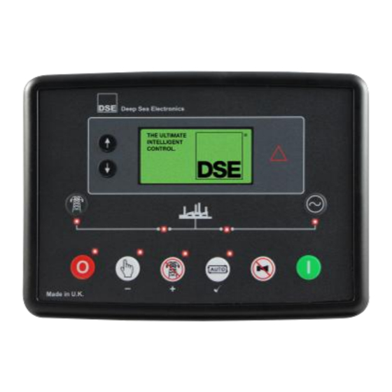
Page 41: Dse6010 Mkii
Description Of Controls 4.1 DSE6010 MKII Menu Module Fault LED. Will be Navigation Display constant on warning and flash upon Electrical Trip and Shutdown Fault Close Open Generator Generator (Manual Mode (Manual Mode Only) Only) Stop / Reset Manual Auto... -
Page 42: Dse6020 Mkii
Description Of Controls 4.2 DSE6020 MKII Menu Module Fault LED. Will be Navigation Display constant on warning and flash upon Electrical Trip and Shutdown Fault Transfer to Transfer to Mains Generator (Manual Mode (Manual Mode Only) Only) Stop / Reset Manual Test Auto... -
Page 43: Control Push-Buttons
Description Of Controls 4.3 CONTROL PUSH-BUTTONS Icon Description Stop / Reset Mode This button places the module into its Stop/Reset Mode . This clears any alarm conditions for which the triggering criteria have been removed. If the engine is running and the module is put into Stop mode, the module automatically instructs the generator to unload (Close Generator and Delayed Load Output 1, 2, 3 &... - Page 44 Description Of Controls Icon Description Auto Mode This button places the module into its Auto Mode . This mode allows the module to control the function of the generator automatically. The module monitors the remote start input and once a start request is made, the set is automatically started and placed on load (Close Generator and Delayed Load Output 1, 2, 3 &...
- Page 45 This button is only active in the Manual Mode and allows the operator to transfer the load to the generator. Open Generator (DSE6010 MKII Only) This button is only active in the Manual Mode and allows the operator to open the generator breaker and remove the load.
-
Page 46: Module Display
DSE60xx MKII Configuration Software Manual. Inst. Instrumentation Unit Alarm Icon Icon Active Instrumentation Unit Config Mode FPE / Icon Auto Instrumentation Unit Example of DSE6010 MKII Home Page Display Example of DSE6020 MKII Home Page Display 057-230 ISSUE: 1 Page 46 of 100... -
Page 47: Backlight
Description Of Controls BACKLIGHT 4.4.1 The LCD backlight is on if the unit has sufficient voltage while the unit is turned on, unless the unit is cranking for which the backlight is turned off. INSTRUMENTATION ICONS 4.4.2 When viewing instrumentation pages, an icon is displayed in the Inst. Icon section to indicate what section is currently being displayed. -
Page 48: Active Configuration
Description Of Controls ACTIVE CONFIGURATION 4.4.3 An icon is displayed in the Active Config section to indicate the active configuration within the currently selected within the controller. Icon Details Appears when the main configuration is selected. Appears when the alternative configuration is selected. FRONT PANEL EDITOR (FPE) / AUTO RUN ICON 4.4.4 NOTE: For further details about the Front Panel Editor, see the section entitled ‘Front... -
Page 49: Alarm Icons (Protections)
Description Of Controls ALARM ICONS (PROTECTIONS) 4.4.6 An icon is displayed in the Alarm Icon section to indicate the alarm that is current active on the controller. In the event of a warning alarm, the LCD only displays the Alarm Icon. In the event of an electrical trip or shutdown alarm, the module displays the Alarm Icon and the Stop/Reset Mode button LED begins to flash. -
Page 50: Warning Alarm Icons
Description Of Controls 4.4.6.1 WARNING ALARM ICONS Warnings are non-critical alarm conditions and do not affect the operation of the generator system, they serve to draw the operators attention to an undesirable condition. By default, warning alarms are self-resetting when the fault condition is removed. However enabling all warnings are latched causes warning alarms to latch until reset manually. -
Page 51: Electrical Trip Alarm Icons
Description Of Controls 4.4.6.2 ELECTRICAL TRIP ALARM ICONS NOTE: The alarm condition must be rectified before a reset takes place. If the alarm condition remains, it is not possible to reset the unit (The exception to this is the Low Oil Pressure alarm and similar active from safety on alarms, as the oil pressure is low with the engine at rest). -
Page 52: Shutdown Alarm Icons
Description Of Controls 4.4.6.3 SHUTDOWN ALARM ICONS NOTE: The alarm condition must be rectified before a reset takes place. If the alarm condition remains, it is not be possible to reset the unit (The exception to this is the Low Oil Pressure alarm and similar active from safety on alarms, as the oil pressure is low with the engine at rest). - Page 53 Description Of Controls Icon Fault Description Generator Under The generator output frequency has fallen below the pre-set alarm Frequency setting after the Safety On timer has expired. Generator Over The generator output frequency has risen above the pre-set alarm Frequency setting.
-
Page 54: Viewing The Instrument
Description Of Controls 4.5 VIEWING THE INSTRUMENT PAGES NAVIGATION MENU 4.5.1 To enter the navigation menu, press both the (up) and (down) buttons simultaneously. To select the required icon, press the (up) button to cycle right or the (down) button to cycle left until the desired instrumentation section is reached. -
Page 55: General Navigation
Description Of Controls GENERAL NAVIGATION 4.5.2 NOTE: For further details of module configuration, refer to DSE Publication: 057-223 DSE60xx MKII Configuration Software Manual. It is possible to scroll through the display to view different pages of information by repeatedly operating (up) or (down) naviagation buttons. -
Page 56: Home
Description Of Controls HOME 4.5.3 This is the page that is displayed when no other page has been selected and is automatically displayed after a period of inactivity (Page Delay Timer) of the module facia buttons. It also contains the voltage reading of the generator and mains that is measured from the module’s voltage inputs. Mains Generator Voltage... -
Page 57: Mains (Dse6020 Mkii Only)
Description Of Controls MAINS (DSE6020 MKII ONLY) 4.5.5 These pages contain electrical values of the mains, measured or derived from the module’s voltage inputs. Mains Voltage (ph-N) Mains Voltage (ph-ph) Mains Frequency LOAD 4.5.6 These pages contain electrical values of the load, measured or derived from the module’s voltage and current inputs. -
Page 58: Engine
Description Of Controls ENGINE 4.5.7 These pages contain instrumentation gathered about the engine measured or derived from the module’s inputs, some of which may be obtained from the engine ECU. 1500 Engine Speed Engine Run Time Engine Battery Volts ... -
Page 59: Engine Dtc (Ecu Alarms)
Description Of Controls ENGINE DTC (ECU ALARMS) 4.5.9 NOTE: For details on these code meanings, refer to the ECU instructions provided by the engine manufacturer, or contact the engine manufacturer for further assistance. NOTE: For further details on connection to electronic engines, refer to DSE Publication: 057-004 Electronic Engines And DSE Wiring If the DSE module is connected to an ECU, This page contains active Diagnostic Trouble Codes (DTC) only if the engine ECU generating a fault code. - Page 60 Description Of Controls Icon Fault DTC Description The engine ECU has detected a fault not recognised by the DSE Check Engine Fault module, contact engine manufacturer for support. The engine ECU has detected that the engine oil pressure has fallen Low Oil Pressure below its configured low oil pressure alarm level.
-
Page 61: Event Log
Description Of Controls EVENT LOG 4.5.10 NOTE: For further details of module configuration, refer to DSE Publication: 057-223 DSE60xx MKII Configuration Software Manual. This module’s event log contains a list of the last 50 recorded events and the engine hours at which they occurred. -
Page 62: Viewing The Event Log
Description Of Controls 4.5.10.1 VIEWING THE EVENT LOG To view the event log, press both (up) and (down) buttons simultaneously, the navigation menu is then displayed. Once entered, cycle to the event log ( ) section and enter. To view the event log, repeatedly press the (up) or (down) buttons until the LCD screen displays the desired event. -
Page 63: Operation
Operation 5 OPERATION NOTE: The following descriptions detail the sequences followed by a module containing the standard ‘factory configuration’. Always refer to your configuration source for the exact sequences and timers observed by any particular module in the field. 5.1 QUICKSTART GUIDE This section provides a quick start guide to the module’s operation. -
Page 64: Stopping The Engine
Operation STOPPING THE ENGINE 5.1.2 NOTE: For further details, see the section entitled ‘OPERATION’ elsewhere in this manual. Select Stop/Reset mode. The generator is stopped 057-230 ISSUE: 1 Page 64 of 100... -
Page 65: Stop/Reset Mode
Operation 5.2 STOP/RESET MODE NOTE: If a digital input configured to Panel Lock is active, changing module modes is not possible. Viewing the instruments and event logs is NOT affected by Panel Lock. NOTE: For further details of module configuration, refer to DSE Publication: 057-223 DSE60xx MKII Configuration Software Manual. -
Page 66: Manual Mode
Operation 5.3 MANUAL MODE NOTE: If a digital input configured to Panel Lock is active, changing module modes is not be possible. Viewing the instruments and event logs is NOT affected by panel lock. Manual Mode is activated by pressing the Manual Mode button. -
Page 67: Engine Running
Once the generator has been placed on load, it is not automatically removed. To manually remove the load either: Press the Open Generator (DSE6010 MKII Only) or Transfer to Mains (DSE6020 MKII Only) button Press the Auto Mode button to return to automatic mode. -
Page 68: Test Mode
Operation 5.4 TEST MODE NOTE: If a digital input configured to Panel Lock is active, changing module modes is not be possible. Viewing the instruments and event logs is NOT affected by Panel Lock. Test Mode is activated by pressing the Test Mode button. -
Page 69: Engine Running
Once the generator has been placed on load, it is not automatically removed. To manually remove the load either: Press the Manual Mode button followed by the Open Generator (DSE6010 MKII Only) or Transfer to Mains (DSE6020 MKII Only) button. Press the Auto Mode button to return to automatic mode. -
Page 70: Automatic Mode
Operation 5.5 AUTOMATIC MODE NOTE: If a digital input configured to external Panel Pock is active, changing module modes is not possible. Viewing the instruments and event logs is NOT affected by Panel Lock. Auto Mode is activated by pressing the Auto Mode button. -
Page 71: Engine Running
Operation ENGINE RUNNING 5.5.3 NOTE: The load transfer signal remains inactive until the Oil Pressure has risen. This prevents excessive wear on the engine. Once the engine is running and all starting timers have expired, the animated Engine Running icon is displayed. -
Page 72: Maintenance Alarm
Operation 5.6 MAINTENANCE ALARM Depending upon module configuration one or more levels of engine maintenance alarm may occur based upon a configurable schedule. Example 1 Screen capture from DSE Configuration Suite Software showing the configuration of the Maintenance Alarm for Oil, Air and Fuel. -
Page 73: Scheduler
Operation 5.7 SCHEDULER The controller contains an inbuilt exercise run scheduler, capable of automatically starting and stopping the set. Up to 8 scheduled start/stop sequences can be configured to repeat on a 7-day or 28-day cycle. Scheduled runs may be on load or off load depending upon module configuration. Example Screen capture from DSE Configuration Suite Software showing the configuration of the... -
Page 74: Front Panel Configuration
Front Panel Configuration 6 FRONT PANEL CONFIGURATION This configuration mode allows the operator to fully configure the module through its display without the use of the DSE Configuration Suite PC Software. Use the module’s facia buttons to traverse the menu and make value changes to the parameters: Next Section (101→201→301) Previous Section... -
Page 75: Accessing The Front Panel Configuration Editor
Front Panel Configuration 6.1 ACCESSING THE FRONT PANEL CONFIGURATION EDITOR NOTE: Pressing and holding the navigation buttons provides the auto-repeat functionality. Values can be changed quickly by holding the navigation buttons for a prolonged period of time. NOTE: The editor automatically exits after 5 minutes of inactivity to ensure security. NOTE: The PIN number is not set by DSE when the module leaves the factory. -
Page 76: Adjustable Parameters
Front Panel Configuration 6.2 ADJUSTABLE PARAMETERS MODULE SETTINGS 6.2.1 Functionality in DSE6010 MKII & DSE6020 MKII Functionality in DSE6020 MKII only Configuration Parameters – Module (Page 1) Contrast 0 (%) Fast Loading Enabled On (1), Off (0) All Warnings Latched... -
Page 77: Input Settings
Front Panel Configuration INPUT SETTINGS 6.2.3 Configuration Parameters – Inputs (Page 3) Digital Input A Source 0 (Input Source) Digital Input A Polarity 0 (Polarity) Digital Input A Action (If Source = User Config) 0 (Action) Digital Input A Arming (If Source = User Config) 0 (Arming) Digital Input A Activation Delay (If Source = User Config) Digital Input B Source... -
Page 78: Output Settings
Front Panel Configuration OUTPUT SETTINGS 6.2.4 Functionality in DSE6010 MKII & DSE6020 MKII Functionality in DSE6020 MKII only Configuration Parameters – Outputs (Page 4) Digital Output A Source 0 (Output Source) Digital Output A Polarity 0 (Output Polarity) Digital Output B Source... -
Page 79: Generator Settings
Front Panel Configuration GENERATOR SETTINGS 6.2.6 Configuration Parameters – Generator (Page 6) Alternator Fitted On (1), Off (0) Alternator Poles Under Voltage Shutdown Enable On (1), Off (0) Under Voltage Trip Shutdown Under Voltage Warning Enable On (1), Off (0) Under Voltage Warning Trip RESERVED Loading Voltage... -
Page 80: Mains Settings
Front Panel Configuration MAINS SETTINGS 6.2.7 Functionality in DSE6010 MKII & DSE6020 MKII Functionality in DSE6020 MKII only Configuration Parameters – Mains (Page 7) AC System 0 (AC System) Mains Failure Detection On (1), Off (0) Immediate Mains Dropout On (1), Off (0) -
Page 81: Engine Settings
Front Panel Configuration ENGINE SETTINGS 6.2.8 Configuration Parameters – Engine (Page 8) Start Attempts Over Speed Overshoot Over Speed Delay Gas Choke Timer (Gas Engine Only) Gas On Delay (Gas Engine Only) Gas Ignition Off Delay (Gas Engine Only) Crank Disconnect On Oil Pressure Enable On (1), Off (0) Check Oil Pressure Prior To Starting On (1), Off (0) -
Page 82: Analogue Inputs Settings
Front Panel Configuration ANALOGUE INPUTS SETTINGS 6.2.9 Configuration Parameters – Analogue Inputs (Page 9) Low Oil Pressure Enable On (1), Off (0) Low Oil Pressure Trip 0 Bar Oil Pressure Sender Open Circuit On (1), Off (0) Analogue Input A Sensor Usage Digital Input (0), Flexible (1), Oil Pressure (3) Sensor Analogue Input A Flexible Senor Type 0 (Sensor Type) - Page 83 Front Panel Configuration Configuration Parameters – Analogue Inputs (Page 9) Fuel Sensor C Low Pre-Alarm Delay Fuel Sensor C High Pre-Alarm Enable On (1), Off (0) Fuel Sensor C High Pre-Alarm Return Fuel Sensor C High Pre-Alarm Trip Fuel Sensor C High Pre Alarm Delay Fuel Sensor C High Alarm Action 0 (Action) Fuel Sensor C High Alarm Trip...
-
Page 84: Scheduler Settings
Front Panel Configuration SCHEDULER SETTINGS 6.2.10 Configuration Parameters – Scheduler (Page 10) 1001 Enable Scheduler On (1), Off (0) 1002 Schedule Run On or Off Load On (1), Off (0) Weekly (0), Schedule Period 1003 Monthly (1) 1004 Scheduler (1) Start Time 0:00:00 1005 Scheduler (1) Start Day... -
Page 85: Maintenance Alarm Settings
Front Panel Configuration MAINTENANCE ALARM SETTINGS 6.2.12 Configuration Parameters – Maintenance Alarms (Page 12) 1201 Oil Maintenance Alarm Enable On (1), Off (0) 1202 Oil Maintenance Alarm Action 0 (Action) 1203 Oil Maintenance Alarm Engine Hours 1204 Air Maintenance Alarm Enable On (1), Off (0) 1205 Air Maintenance Alarm Action... - Page 86 Front Panel Configuration Functionality in DSE6010 MKII & DSE6020 MKII Functionality in DSE6020 MKII only Configuration Parameters – Alternate Configuration (Page 20) 2024 CT Primary 2025 Full Load Rating 2026 Immediate Over Current On (1), Off (0) 2027 Delayed Over Current Alarm...
-
Page 87: Selectable Parameter Settings
Front Panel Configuration 6.3 SELECTABLE PARAMETER SETTINGS INPUT SOURCES 6.3.1 Functionality in DSE6010 MKII & DSE6020 MKII Functionality in DSE6020 MKII only Input Sources User Configured Alarm Mute Alarm Reset Alternative Configuration Auto Restore Inhibit Auto Start Inhibit Auxiliary Mains Fail... -
Page 88: Output Sources
Front Panel Configuration OUTPUT SOURCES 6.3.2 Functionality in DSE6010 MKII & DSE6020 MKII Functionality in DSE6020 MKII only Output Sources Not Used Air Flap Relay Audible Alarm Battery Over Volts Warning Battery Under Volts Warning CAN ECU Data Fail CAN ECU Error... - Page 89 Front Panel Configuration Functionality in DSE6010 MKII & DSE6020 MKII Functionality in DSE6020 MKII only Output Sources Oil Pressure Sender Open Circuit Open Gen Output Open Gen Output Pulse Open Mains Output Open Mains Output Pulse Over Frequency Shutdown Over Speed Shutdown...
-
Page 90: Alarm Action
Front Panel Configuration ALARM ACTION 6.3.3 Alarm Action Index Action Electrical Trip Shutdown Warning FLEXIBLE SENSOR ALARM ACTION 6.3.4 Flexible Sensor Alarm Action Index Action None Shutdown Electrical Trip POWER UP MODE 6.3.5 Power Up Mode Index Mode Stop Manual Auto SENSOR TYPE 6.3.6... -
Page 91: Digital Input Alarm Arming
Front Panel Configuration DIGITAL INPUT ALARM ARMING 6.3.8 Digital Input Alarm Arming Index Arming Always From Safety On From Starting Never DIGITAL INPUT POLARITY 6.3.9 Digital Input Polarity Index Polarity Close to Activate Open to Activate DIGITAL OUTPUT POLARITY 6.3.10 Output Polarity Index Polarity... -
Page 92: Pressure Sensor List
Front Panel Configuration PRESSURE SENSOR LIST 6.3.12 Pressure Sensor List Index Type Not used Dig Closed for Alarm Dig Open for Alarm VDO 5 Bar VDO 10 Bar Datcon 5 Bar Datcon 10 Bar Datcon 7 Bar Murphy 7 Bar CMB812 Veglia User Defined... -
Page 93: Commissioning
Commissioning 7 COMMISSIONING NOTE: If Emergency Stop feature is not required, link the input to the DC Positive. Before the system is started, it is recommended that the following checks are made:- The unit is adequately cooled and all the wiring to the module is of a standard and rating compatible with the system. -
Page 94: Fault Finding
Commissioning 8 FAULT FINDING 8.1 STARTING Symptom Possible Remedy Unit is inoperative Check the battery and wiring to the unit. Check the DC supply. Check the DC fuse. Read/Write configuration does not operate Unit shuts down Check DC supply voltage is not above 35 Volts or below 9 Volts Check the operating temperature is not above 70°C. -
Page 95: Alarms
Commissioning 8.3 ALARMS Symptom Possible Remedy Low oil Pressure fault Check engine oil pressure. Check oil pressure switch/sensor and operates after engine has wiring. Check configured polarity (if applicable) is correct (i.e. fired Normally Open or Normally Closed) or that sensor is compatible with the module and is correctly configured. -
Page 96: Miscellaneous
Commissioning 8.6 MISCELLANEOUS NOTE: The above fault finding is provided as a guide check-list only. As the module can be configured to provide a wide range of different features, always refer to the source of your module configuration if in doubt. Symptom Possible Remedy Module appears to ‘revert’... -
Page 97: Maintenance, Spares, Repair And Servicing
9.1 PURCHASING ADDITIONAL CONNECTOR PLUGS FROM DSE If you require additional plugs from DSE, please contact our Sales department using the part numbers below. PACK OF PLUGS 9.1.1 Module Type Plug Pack Part Number DSE6010 MKII 100-400-69 DSE6020 MKII 100-400-66 INDIVIDUAL PLUGS 9.1.2 Module Terminal Designation Plug Description Part No. -
Page 98: Warranty
Warranty, Disposal 10 WARRANTY DSE Provides limited warranty to the equipment purchaser at the point of sale. For full details of any applicable warranty, you are referred to our original equipment supplier (OEM) 11 DISPOSAL 11.1 WEEE (WASTE ELECTRICAL AND ELECTRONIC EQUIPMENT) If you use electrical and electronic equipment you must store, collect, treat, recycle and dispose of WEEE separately from your other waste. - Page 99 This Page is Intentionally Left Blank...
- Page 100 This Page is Intentionally Left Blank...
Need help?
Do you have a question about the DSE6010 MKII and is the answer not in the manual?
Questions and answers
I locked my self out of gseL401mk11 controler. But I never sett a code . Actually I set a digital mains input and it altered use of start and auto button ho e do I fix it ?
If the code was never set but the DSE 6010 MKII controller is locked and the digital mains input has altered the function of the Start and Auto buttons, you must return the module to the DSE factory to have the code removed. This procedure cannot be done remotely and involves a charge.
This answer is automatically generated