
Related Manuals for DSEGenset DSE8660


Summary of Contents for DSEGenset DSE8660
- Page 1 DEEP SEA ELECTRONICS PLC DSE8660 Operator Manual Document number 057-120 Author : Anthony Manton DSE8660 Operator Manual Issue 5...
- Page 2 DSE8660 ATS and Mains Controller Operators Manual Deep Sea Electronics Plc Highfield House Hunmanby North Yorkshire YO14 0PH ENGLAND Sales Tel: +44 (0) 1723 890099 Sales Fax: +44 (0) 1723 893303 E-mail: sales@deepseaplc.com Website: www.deepseaplc.com DSE8660 ATS and Mains Controller Operators Manual ©...
-
Page 3: Table Of Contents
DSE8660 ATS and Mains Controller Operators Manual TABLE OF CONTENTS Section Page BIBLIOGRAPHY ....................6 INSTALLATION INSTRUCTIONS ..................6 TRAINING GUIDES ......................6 MANUALS ..........................6 INTRODUCTION ....................7 SPECIFICATIONS .................... 8 TERMINAL SPECIFICATION ....................8 POWER SUPPLY REQUIREMENTS .................. 8 GENERATOR BUS AND MAINS VOLTAGE / FREQUENCY SENSING ...... - Page 4 DSE8660 ATS and Mains Controller Operators Manual 4.2.6.1 NEGATIVE EARTH ..........................43 4.2.6.2 POSITIVE EARTH ..........................43 4.2.6.3 FLOATING EARTH ..........................43 TYPICAL ARRANGEMENT OF DSENET® ............... 44 DESCRIPTION OF CONTROLS ..............45 DSE8660 AMF CONTROL MODULE ................45 QUICKSTART GUIDE ......................47 5.2.1...
- Page 5 DSE8660 ATS and Mains Controller Operators Manual FAULT FINDING ..................79 MAINTENANCE, SPARES, REPAIR AND SERVICING ......80 12.1.1.1 PACK OF PLUGS ..........................80 12.1.1.2 INDIVIDUAL PLUGS ........................80 12.2 PURCHASING ADDITIONAL FIXING CLIPS FROM DSE ..........80 12.3 PURCHASING ADDITIONAL SEALING GASKET FROM DSE ........80 12.4...
-
Page 6: Bibliography
Installation instructions are supplied with the product in the box and are intended as a ‘quick start’ guide only. DSE PART DESCRIPTION 053-069 DSE8610 Installation Instructions 053-070 DSE8660 Installation Instructions 053-032 DSE2548 LED Expansion Annunciator Installation Instructions 053-033 DSE2130 Input Expansion Installation Instructions 053-034 DSE2157 Output Expansion Installation Instructions 1.2 TRAINING GUIDES... -
Page 7: Introduction
OEM greater flexibility in the choice of controller to use for a specific application. The DSE8660 module has been designed to monitor the mains (utility) supply and automatically start/stop one ore more generator sets equipped with DSE8610 controllers depending upon the status of the mains (utility) supply. -
Page 8: Specifications
Specifications 3 SPECIFICATIONS 3.1 TERMINAL SPECIFICATION Connection type Two part connector. Male part fitted to module • Female part supplied in module • packing case - Screw terminal, rising clamp, no internal spring. Example showing cable entry and screw Minimum cable size 0.5mm²... -
Page 9: Mains And Load Current Sensing
Specifications 3.4 MAINS AND LOAD CURRENT SENSING Measurement type True RMS conversion Sample Rate 5KHz or better Harmonics Up to 10 or better Nominal CT secondary rating 1A or 5A (5A recommended) Maximum continuous current Overload Measurement 3 x Nominal CT setting Absolute maximum overload 50A for 1 second Burden... -
Page 10: Outputs
Specifications 3.6 OUTPUTS 3.6.1 OUTPUTS A & B Outputs A & B are not fitted to the DSE8660 controller. 3.6.2 OUTPUTS C & D Type Voltage free relays, fully configurable, normally used for generator bus / mains load switch control. -
Page 11: Communication Ports
External termination required (120Ω) Max common mode offset 70V (on board protection transorb) Max distance 1.2km (¾ mile) MSC Port MSC Port for connection to other DSE8660 and DSE8610 controllers Max distance 240m (133 feet). Use DSE124 to extend this if required. -
Page 12: Usb Connection
3.7.1 USB CONNECTION The USB port is provided to give a simple means of connection between a PC and the DSE8660 series controller. Using the DSE Configuration Suite Software, the operator is then able to control the module, starting or stopping the generator(s), selecting operating modes, etc. -
Page 13: Rs232
Specifications 3.7.3 RS232 The RS232 port on the DSE8600 series controller supports the Modbus RTU protocol. The Gencomm register table for the controller is available upon request from the DSE Technical Support Department. RS232 is for short distance communication (max 15m) and is typically used to connect the DSE86xx series controller to a telephone or GSM modem for more remote communications. - Page 14 Specifications RECOMMENDED EXTERNAL MODEMS: Multitech Global Modem – MultiModem ZBA (PSTN) • DSE Part Number 020-252 (Contact DSE Sales for details of localisation kits for these modems) Wavecom Fastrak Supreme GSM modem kit (PSU, Antenna and modem)* • DSE Part number 0830-001-01 Brodersen GSM Industrial Modem* •...
-
Page 15: Rs485
Specifications 3.7.4 RS485 The RS485 port on the DSE8600 series controller supports the Modbus RTU protocol. The DSE Gencomm register table for the controller is available upon request from the DSE Technical Support Department. RS485 is used for point-to-point cable connection of more than one device (maximum 32 devices) and allows for connection to PCs, PLCs and Building Management Systems (to name just a few devices). -
Page 16: Ethernet
Specifications 3.7.5 ETHERNET The DSE8660 is fitted with ETHERNET socket for connection to LAN (local area networks) Description Do not connect Do not connect Do not connect Do not connect 3.7.5.1 DIRECT PC CONNECTION Requirements • DSE8660 Crossover Ethernet cable (see Below) •... -
Page 17: Connection To Basic Ethernet
NOTE:- This cable can be purchased from any good PC or IT store. 3.7.5.2 CONNECTION TO BASIC ETHERNET Requirements DSE8660 • • Ethernet cable (see below) Working Ethernet (company or home network) • PC with Ethernet port •... -
Page 18: Connection To Company Infrastructure Ethernet
NOTE:- DSE Stock a 2m (2.2yds) Ethernet Cable – Part number 016-137. Alternatively they can be purchased from any good PC or IT store. 3.7.5.3 CONNECTION TO COMPANY INFRASTRUCTURE ETHERNET Requirements DSE8660 • Ethernet cable (see below) • Working Ethernet (company or home network) •... -
Page 19: Connection To The Internet
Specifications Ethernet cable wiring detail 10baseT/100baseT Connection 1 (T568A) Connection 2 (T568A) white/green stripe white/green stripe For the advanced Engineer, this cable green solid green solid has both ends terminated as white/orange stripe white/orange stripe T568A (as shown below) or T568B. blue solid blue solid white/blue stripe... - Page 20 Specifications Ethernet cable wiring detail 10baseT/100baseT Connection 1 (T568A) Connection 2 (T568A) For the advanced white/green stripe white/green stripe Engineer, this cable has both ends green solid green solid terminated as white/orange stripe white/orange stripe T568A (as shown below) or T568B. blue solid blue solid white/blue stripe...
- Page 21 As modem/routers differ enormously in their configuration, it is not possible for DSE to give a complete guide to their use with the DSE8660. However it is possible to give a description of the requirements in generic terms. For details of how to achieve the connection to your modem/router you are referred to the supplier of your modem/router equipment.
-
Page 22: Dsenet® For Expansion Modules
Specifications 3.8 DSENET® FOR EXPANSION MODULES DSENet® is the interconnection cable between the host controller and the expansion module(s) and must not be connect to any device other than DSE equipment designed for connection to the DSENet® Cable type Two core screened twisted pair Cable characteristic impedance 120Ω... -
Page 23: Sounder
Specifications 3.9 SOUNDER DSE8600 Series features an internal sounder to draw attention to warning, shutdown and electrical trip alarms. Sounder level 64db @ 1m 3.9.1 ADDING AN EXTERNAL SOUNDER TO THE APPLICATION Should an external alarm or indicator be required, this can be achieved by using the DSE Configuration Suite PC software to configure an auxiliary output for Audible Alarm, and by configuring an auxiliary input for Alarm Mute (if required). -
Page 24: Dimensions And Mounting
Specifications 3.10 DIMENSIONS AND MOUNTING 3.10.1 DIMENSIONS 240.0mm x 181.1mm x 41.7mm (9.4” x 7.1” x 1.6”) PANEL CUTOUT 220mm x 160mm (8.7” x 6.3”) WEIGHT 0.7kg (1.4lb) - Page 25 Specifications FIXING CLIPS Supplied fixing clips hold the module into the panel fascia. Withdraw the fixing clip screw (turn anticlockwise) until only the pointed end is protruding from the clip. Insert the three ‘prongs’ of the fixing clip into the slots in the side of the 8600 series module case. •...
-
Page 26: Cable Tie Fixing Points
Specifications 3.10.2 CABLE TIE FIXING POINTS Integral cable tie fixing points are included on the rear of the module’s case to aid wiring. This additionally provides strain relief to the cable loom by removing the weight of the loom from the screw connectors, thus reducing the chance of future connection failures. -
Page 27: Applicable Standards
Specifications 3.11 APPLICABLE STANDARDS This document conforms to BS4884-1 1992 Specification for presentation of essential BS 4884-1 information. BS 4884-2 This document conforms to BS4884-2 1993 Guide to content BS 4884-3 This document conforms to BS4884-3 1993 Guide to presentation BS EN 60068-2-1 -30°C (-22°F) (Minimum temperature) -
Page 28: Enclosure Classifications
Specifications 3.11.1 ENCLOSURE CLASSIFICATIONS IP CLASSIFICATIONS 8600 series specification under BS EN 60529 Degrees of protection provided by enclosures IP65 (Front of module when module is installed into the control panel with the optional sealing gasket). IP42 (front of module when module is installed into the control panel WITHOUT being sealed to the panel) First Digit Second Digit Protection against contact and ingress of solid objects... - Page 29 Specifications NEMA CLASSIFICATIONS 8600 series NEMA Rating (Approximate) 12 (Front of module when module is installed into the control panel with the optional sealing gasket). 2 (front of module when module is installed into the control panel WITHOUT being sealed to the panel) NOTE: - There is no direct equivalence between IP / NEMA ratings.
-
Page 30: Installation
Installation 4 INSTALLATION The DSE8600 Series module is designed to be mounted on the panel fascia. For dimension and mounting details, see the section entitled Specification, Dimension and mounting elsewhere in this document. 4.1 TERMINAL DESCRIPTION 4.1.1 DC SUPPLY, FUEL AND START OUTPUTS Icon DESCRIPTION CABLE... -
Page 31: Magnetic Pickup, Can And Expansion
Installation 4.1.2 MAGNETIC PICKUP, CAN AND EXPANSION DESCRIPTION CABLE NOTES SIZE Not Connected Not Connected Not Connected Not Connected Not Connected Not Connected 0.5mm² DSENet expansion + Use only 120Ω RS485 approved cable AWG 20 0.5mm² DSENet expansion - Use only 120Ω RS485 approved cable AWG 20 0.5mm²... -
Page 32: Load Switching And Mains Voltage Sensing (V1)
Installation 4.1.3 LOAD SWITCHING AND MAINS VOLTAGE SENSING (V1) DESCRIPTION CABLE NOTES SIZE 1.0mm Normally configured to control load switching device Output relay C AWG 18 (Recommend 10A fuse) 1.0mm Normally configured to control load switching device Output relay C AWG 18 1.0mm Normally configured to control load switching device... -
Page 33: Mains Current Transformers
Installation 4.1.5 MAINS CURRENT TRANSFORMERS WARNING! - Do not disconnect this plug when the CTs are carrying current. Disconnection will open circuit the secondary of the C.T.’s and dangerous voltages may then develop. Always ensure the CTs are not carrying current and the CTs are short circuit connected before making or breaking connections to the module. -
Page 34: Load Current Transformer
4.1.1.1 ADVANTAGES OF LOAD CT The load CT is only required when there is more than one DSE8660 on the same system. When the load CT is fitted the 8660 transfers the right amount of load to the mains before disconnecting the generator(s), preventing them from being shock loaded. -
Page 35: Configurable Digital Inputs
Installation 4.1.2 CONFIGURABLE DIGITAL INPUTS DESCRIPTION CABLE NOTES SIZE 0.5mm² Configurable digital input A Switch to negative AWG 20 0.5mm² Configurable digital input B Switch to negative AWG 20 0.5mm² Configurable digital input C Switch to negative AWG 20 0.5mm² Configurable digital input D Switch to negative AWG 20... -
Page 36: Rs485 Connector
Installation 4.1.4 RS485 CONNECTOR PIN No NOTES Two core screened twisted pair cable. 120Ω impedance suitable for RS485 use. Recommended cable type - Belden 9841 Max distance 1200m (1.2km) when using Belden 9841 or direct equivalent. Location of RS485 connector Location of RS232 connector 4.1.5 RS232 CONNECTOR... -
Page 37: Typical Wiring Diagrams
Installation 4.2 TYPICAL WIRING DIAGRAMS As every system has different requirements, these diagrams show only a TYPICAL system and do not intend to show a complete system. Genset manufacturers and panel builders may use these diagrams as a starting point; however, you are referred to the completed system diagram provided by your system manufacturer for complete wiring detail. -
Page 38: Phase, 4 Wire
Installation 4.2.1 3 PHASE, 4 WIRE... -
Page 39: Single Mains, Multiple Generators
Installation 4.2.2 SINGLE MAINS, MULTIPLE GENERATORS... -
Page 40: Dual Mains, Multiple Generators
Installation 4.2.3 DUAL MAINS, MULTIPLE GENERATORS... -
Page 41: Multiple Mains, Multiple Generators
Installation 4.2.4 MULTIPLE MAINS, MULTIPLE GENERATORS... -
Page 42: Dsenet
Installation 4.2.5 DSENET® DSENet® is the communication port between the host controller (DSE86xx series) and the expansion device as shown below. Further details are contained within the Specification section of this document and within the operator manual for the specific expansion module you are connecting to. NOTE: Screened 120Ω... -
Page 43: Earth Systems
Installation 4.2.6 EARTH SYSTEMS 4.2.6.1 NEGATIVE EARTH The typical wiring diagrams located within this document show connections for a negative earth system (the battery negative connects to Earth) 4.2.6.2 POSITIVE EARTH When using a DSE module with a Positive Earth System (the battery positive connects to Earth), the following points must be followed: Follow the typical wiring diagram as normal for all sections EXCEPT the earth points •... -
Page 44: Typical Arrangement Of Dsenet
Installation 4.3 TYPICAL ARRANGEMENT OF DSENET® Twenty (20) devices can be connected to the DSENet®, made up of the following devices : Device Max number supported DSE2130 Input Expansion DSE2131 Input Expansion DSE2133 Input Expansion DSE2152 Output Expansion DSE2157 Output Expansion DSE2548 LED Expansion NOTE : DSE8600 series does not support the 2510/2520 display modules. -
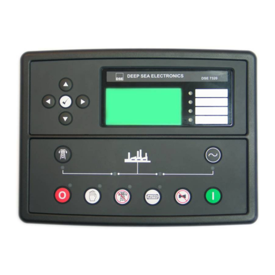
Page 45: Description Of Controls
Description of Controls 5 DESCRIPTION OF CONTROLS The following section details the function and meaning of the various controls on the module. 5.1 DSE8660 AMF CONTROL MODULE Menu navigation buttons Main status and Transfer to Four configurable instrumentation display mains (Manual... - Page 46 Description of Controls Mains Available LED. On when the mains is within limits and able to take load. Bus Available LED. On when the generator is within limits and able to Close Mains LED. take load. Close Bus LED. On When The Mains Is On When The Bus Is On On Load.
-
Page 47: Quickstart Guide
5.2.1 STARTING THE ENGINE(S) Ensure all DSE8610 generator controllers are in the AUTO mode Then, select MANUAL mode on the DSE8660 …then press the Start button to crank the engine(s). NOTE: For further details, see the section entitled ‘OPERATION’ elsewhere in this manual. -
Page 48: Stopping The Engine(S)
Description of Controls 5.2.2 STOPPING THE ENGINE(S) With the DSE8610’s already in the AUTO mode, select Stop/Reset mode on all DSE8660’s in the system. The generator(s) is stopped. NOTE: For further details, see the section entitled ‘OPERATION’ elsewhere in this manual. -
Page 49: Viewing The Instrument
Description of Controls 5.3 VIEWING THE INSTRUMENT PAGES It is possible to scroll to display the different pages of information by repeatedly operating the next / previous page buttons If you want to view one of the instrument pages towards the end of the list, it may be quicker to scroll left through the pages rather than right! -
Page 50: Status
Description of Controls 5.3.1 STATUS This is the ‘home’ page, the page that is displayed when no other page has been selected, and the page that is automatically displayed after a period of inactivity (LCD Page Timer) of the module control buttons. This page is configurable using the DSE Configuration Suite Software. -
Page 51: Mains
Description of Controls 5.3.2 MAINS Mains Volts (L1-N, L2-N, L3-N) Mains Volts (L1-L2, L2-L3, L3-L1) Mains Hz Mains Amps Mains kW Mains kVA Mains pf Mains kVAr Mains kWh, kVAh, kVArh Mains configuration type Synchroscope Battery Voltage 5.3.3 BUS Bus volts (L1-N, L2-N, L3-N) Bus volts (L1-L2, L2-L3, L3-L1) Bus Hz Bus kW... -
Page 52: Serial Port
Description of Controls 5.3.4 SERIAL PORT This section is included to give information about the currently selected serial port and external modem (if connected). The items displayed on this page will change depending upon configuration of the module. You are referred to your system supplier for further details. - Page 53 Description of Controls Example 1 continued – Modem diagnostics NOTE:- Modem diagnostic screens are available on 73xx module versions 5 and above only. The modem screens appear only when the module has been configured for use with a modem. Modem diagnostic screens are included; press when viewing the Serial Port instrument to cycle the available screens.
- Page 54 Description of Controls Modem Setup Sequence If the Modem and DSE8600 series communicate successfully: In case of communication failure between the modem and DSE8600 series module, the modem is automatically reset and initialisation is attempted once more: In the case of a module that is unable to communicate with the modem, the display will continuously cycle between ‘Modem Reset’...
- Page 55 Description of Controls Example 4 - Module RS485 port configured for connection to a modbus master. DSE86xx series modules operate as a modbus RTU slave device. In a modbus system, there can be only one Master, typically a PLC, HMI system or PC SCADA system.
-
Page 56: About
Description of Controls 5.3.5 ABOUT Contains important information about the module and the firmware versions. This information may be asked for when contacting DSE Technical Support Department for advice. • Module Type (i.e. 8610, 8660) Application Version – The version of the module’s main firmware file – Updatable using the Firmware •... -
Page 57: Data Logging
Description of Controls 5.3.5.2 DATA LOGGING PAGES The DSE data logging pages show information depending on the configuration in the module. Location of stored data. Data Logging Internal module memory or external Log to internal memory USB memory. Logging active No USB drive present If data logging is active or inactive Inserting a USB drive to the host USB will display the following change to the page. -
Page 58: Viewing The Event Log
Description of Controls 5.4 VIEWING THE EVENT LOG The DSE8600 series modules maintain a log of past alarms and/or selected status changes. The log size has been increased in the module over past module updates and is always subject to change. At the time of writing, the 86xx series log is capable of storing the last 250 log entries. -
Page 59: User Configurable Indicators
Description of Controls 5.5 USER CONFIGURABLE INDICATORS These LEDs can be configured by the user to indicate any one of 100+ different functions based around the following:- • Indications - Monitoring of a digital input and indicating associated functioning user’s equipment - Such as Battery Charger On or Louver’s Open, etc. -
Page 60: Controls
Description of Controls 5.6 CONTROLS Stop / Reset This button places the module into its Stop/Reset mode. This will clear any alarm conditions for which the triggering criteria have been removed. If the engine(s) is(are) running and the module is in Stop mode, the module will automatically instruct the changeover device to unload the generator bus (‘Close Bus becomes inactive (if used)). - Page 61 Description of Controls CLOSE MAINS This push button is used to control the closure of the mains load switching device and has two modes of operation : 1. Synchronising is NOT enabled. Pressing this button when the mains is available off load and in MANUAL mode, the bus load switch is opened and the mains load switch is closed.
-
Page 62: Operation
Operation 6 OPERATION The following description details the sequences followed by a module containing the standard ‘factory configuration’. Remember that if you have purchased a completed generator set or control panel from your supplier, the module’s configuration will probably have been changed by them to suit their particular requirements. Always refer to your configuration source for the exact sequences and timers observed by any particular module in the field. -
Page 63: Stop Mode
Any latched alarms (electrical trip) that have been cleared are reset when STOP mode is entered. The engine will not be started by the DSE8660 when in STOP mode. If remote start signals are given or the mains supply fails, the start request is not sent to the engines until AUTO mode is entered. -
Page 64: Engine Running
Once the generator bus becomes available, the load is transferred. If required, the generator bus is first synchronised with the mains supply. This operation is automatic, using the MSC data link. Load ramping takes place when appropriate, the DSE8660 controls the generator(s) bus to provide the configured power to the load and/or mains supply. -
Page 65: Manual Mode
Operation 6.4 MANUAL MODE NOTE: If a digital input configured to panel lock is active, changing module modes will not be possible. Viewing the instruments and event logs is NOT affected by panel lock. Activate Manual mode be pressing the pushbutton. -
Page 66: Test Mode
Operation 6.5 TEST MODE NOTE: If a digital input configured to panel lock is active, changing module modes will not be possible. Viewing the instruments and event logs is NOT affected by panel lock. Activate test mode be pressing the pushbutton. -
Page 67: Multiple Mains Operation
Operation 6.6 MULTIPLE MAINS OPERATION In a multiple mains system, the generator sets are controlled by more than one 8660 mains controller and used to provide power to multiple loads. Should one or more of the mains supplies fail, the generators (controlled by DSE 8610 modules) are started and supply power to the load. -
Page 68: 8660 Load Ct
Operation 6.6.2 8660 LOAD CT The 8660 controller incorporates an optional (but recommended) extra CT measuring the size of the load. Used in conjunction with the CTs measuring the amount of load on the mains supply, this CT allows the 8660 to determine what portion of the load is being supplied by the generators. -
Page 69: Protections
Protections 7 PROTECTIONS When an alarm is present, the Audible Alarm will sound and the Common alarm LED if configured will illuminate. The audible alarm can be silenced by pressing the Mute button The LCD display will jump from the ‘Information page’ to display the Alarm Page Number of present alarms. -
Page 70: Warnings
Protections 7.2 WARNINGS Warnings are non-critical alarm conditions and do not affect the operation of the generator system, they serve to draw the operators attention to an undesirable condition. In the event of an alarm the LCD will jump to the alarms page, and scroll through all active warnings and shutdowns. -
Page 71: Electrical Trips
Protections 7.3 ELECTRICAL TRIPS Electrical trips are latching and stop the Generator but in a controlled manner. On initiation of the electrical trip condition the module will de-energise the ‘Close Generator’ Output to remove the load from the generator. Once this has occurred the start request is removed. -
Page 72: Scheduler
Scheduler 8 SCHEDULER DSE8600 Series contains an inbuilt exercise run scheduler, capable of automatically starting and stopping the set. Up to 16 scheduled start/stop sequences can be configured to repeat on a 7-day or 28-day cycle. Scheduled runs may be on load or off load depending upon module configuration. Example Screen capture from DSE Configuration Suite Software showing the configuration of the Exercise... -
Page 73: Front Panel Configuration
Front Panel Configuration 9 FRONT PANEL CONFIGURATION This configuration mode allows the operator limited customising of the way the module operates. Use the module’s navigation buttons to traverse the menu and make value changes to the parameters: Increase value / next item Previous page Decrease value / next item... -
Page 74: Accessing The Main Front Panel Configuration Editor
Front Panel Configuration 9.1 ACCESSING THE MAIN FRONT PANEL CONFIGURATION EDITOR Ensure the engine is at rest and the module is in STOP mode by pressing the Stop/Reset button. Press the Stop/Reset and Info buttons simultaneously. If a module security PIN has been set, the PIN number request is then shown : Press , the first ‘#’... -
Page 75: Editing A Parameter
Front Panel Configuration 9.1.1 EDITING A PARAMETER Enter the editor as described above. Press the (left) or (right) buttons to cycle to the section you wish to view/change. Press the (up or down) buttons to select the parameter you wish to view/change within the currently selected section. -
Page 76: Adjustable Parameters
Front Panel Configuration 9.1.2 ADJUSTABLE PARAMETERS Front Panel Configuration Editor Section Parameter as shown on display Factory Settings Display Contrast Language English, others. hh:mm Current Date and Time LCD Page Timer Timers 2s s s s Scroll Delay Battery Under Voltage Warning Delay Battery Over Voltage Warning Delay Start Delay Off Load Start Delay On Load... -
Page 77: Accessing The 'Running' Configuration Editor
Front Panel Configuration 9.2 ACCESSING THE ‘RUNNING’ CONFIGURATION EDITOR The ‘running’ editor can be entered while the engine is running. All protections remain active if the engine is running while the running editor is entered. Press and hold the button to enter the running editor. 9.2.1 EDITING A PARAMETER Enter the editor as described above. -
Page 78: Commissioning
Commissioning and Fault Finding 10 COMMISSIONING 10.1.1 PRE-COMMISSIONING Before the system is started, it is recommended that the following checks are made:- 1. The unit is adequately cooled and all the wiring to the module is of a standard and rating compatible with the system. -
Page 79: Fault Finding
Commissioning and Fault Finding 11 FAULT FINDING SYMPTOM POSSIBLE REMEDY Unit is inoperative Check the battery and wiring to the unit. Check the DC supply. Check the DC fuse. Read/Write configuration does not operate Unit shuts down Check DC supply voltage is not above 35 Volts or below 9 Volts Check the operating temperature is not above 70°... -
Page 80: Maintenance, Spares, Repair And Servicing
057-513 DSE8660 007-514 12.1.1.2 INDIVIDUAL PLUGS 8600 series terminal designation Plug description Part No. 1-11 11 way 5.08mm 007-451 15-19 Not fitted to DSE8660 22-30 9 way 5.08mm 007-167 39-46 8 way 7.62mm 007-454 47-50 4 way 7.62mm 007-171 51-56 6 way 5.08mm... -
Page 81: Expansion Modules
Maintenance, Spares, Repair and Servicing 12.4 EXPANSION MODULES NOTE: A maximum of twenty (20) expansion modules can be connected to the DSENet®. NOTE: DSENet® utilises an RS485 connection. Using Belden 9841 (or equivalent) cable allows for the expansion cable to be extended to a maximum of 1.2km. DSE Stock and supply Belden 9841 cable. -
Page 82: Warranty
Warranty & Disposal 13 WARRANTY DSE provides limited warranty to the equipment purchaser at the point of sale. For full details of any applicable warranty, you are referred to your original equipment supplier (OEM). 14 DISPOSAL 14.1 WEEE (WASTE ELECTRICAL AND ELECTRONIC EQUIPMENT) Directive 2002/96/EC If you use electrical and electronic equipment you must store, collect, treat, recycle and dispose of WEEE separately from your other waste. - Page 83 This page is intentionally left blank...
- Page 84 This page is intentionally left blank...
Need help?
Do you have a question about the DSE8660 and is the answer not in the manual?
Questions and answers