Table of Contents
Advertisement
Advertisement
Table of Contents

Related Manuals for Continental Refrigerator Perma-Crimp PC125


Summary of Contents for Continental Refrigerator Perma-Crimp PC125
- Page 1 PC125 and PC125M Operators Manual C125 125M O perators Manual Perma-Crimp™ Hydraulic Hose Crimpers Hydraulic Hose Crimpers PC125 and PC125M Operators Manual PC125 and PC125M Operators Manual www.contitech.us www.continental-industry.com...
-
Page 2: Pc125 / Pc125M Safety Precautions
PC125 / 125M Safety Precautions SAFETY PRECAUTIONS • READ INSTRUCTIONS AND IDENTIFY ALL COMPONENT PARTS BEFORE USING CRIMPER. • CRIMPER CAN PRODUCE 60 TONS OF FORCE. KEEP BOTH HANDS AWAY FROM PINCH POINTS. • CONSULT THE CONTINENTAL CONTITECH CRIMP SPECIFICATION MANUAL FOR CORRECT CRIMPER SETTINGS AND CRIMP MEASUREMENTS. -
Page 3: Table Of Contents
Table Of Content PC125 / PC125M SAFETY PRECAUTIONS-----------------------------------------------------------------------------------------------------------2 PC125 / 125M EQUIPMENT WARNING-----------------------------------------------------------------------------------------------------------------2 PC125 / PC125M SPECIFICATIONS----------------------------------------------------------------------------------------------------------------------4 PC125 / PC125M COMPONENT IDENTIFICATION---------------------------------------------------------------------------------------------------5 AVAILABLE ACCESSORIES FOR PC125 / 125M SERIES CRIMPERS-----------------------------------------------------------------------6 PC125 / PC125M FEATURES------------------------------------------------------------------------------------------------------------------7 PC125 / PC125M QUICK START GUIDE-----------------------------------------------------------------------------------------------------8 PC125 / PC125M LUBRICATION PROCEDURE-----------------------------------------------------------------------------------------------------9 PC125 / PC125M CRIMPING PROCEDURE------------------------------------------------------------------------------------------10 PC125 CALIBRATION CHECK-------------------------------------------------------------------------------------------------------------------------15... -
Page 4: Pc125 / Pc125M Specifications
PC125 / 125M Specifications D160 SERIES / D165 SPECIFICATIONS Die Series-------------------------------------------------------------------------------------------------------------------------PC125 Series Maximum Cylinder Force---------------------------------------------------------------------------------------------------------------60 Ton Maximum Hose Diameter (2 Wire)----------------------------------------------------------------------------------------------1 1/4 Inch Maximum Hose Diameter (4 Wire)----------------------------------------------------------------------------------------------1 1/4 Inch Maximum Hose Diameter (6 Wire)---------------------------------------------------------------------------------------------------1 Inch Crimper Depth - PC125 Series-------------------------------------------------------------------------------------------------22.5 Inches - PC125M Series-------------------------------------------------------------------------------------------------17 Inches Crimper Width - PC125 Series----------------------------------------------------------------------------------------------------13 Inches - PC125M Series --------------------------------------------------------------------------------------------10.25 Inches... -
Page 5: Pc125 / Pc125M Component Identification
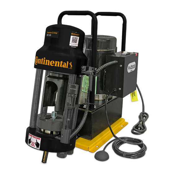
PC125 / 125M Component Identification CONTINENTAL QR CODE 110 VOLT VALPOWER HYDRAULIC PUMP ® 60 TON HYDRAULIC CYLINDER POWER SWITCH RETRACTION STOP ELECTRICAL ENCLOSURE MICRO-CRIMP ADJUSTER REMOVABLE PUSHER VOLTAGE TAG W/ MAGNETS 1 GALLON RESERVOIR NOTCHED ELECTRICAL CORD COMPRESSION RING PNEUMATIC START/STOP SWITCH PC125 DIE SET CALIBRATION... -
Page 6: Available Accessories For Pc125 / 125M Series Crimpers
Available Accessories For PC125 / 125M Series Crimpers Removable Pusher Notched Compression Ring Pressure Plate Coupling Stop CRIMPX Die Lubricant Oil: (Included) (Included) (Included) (Included only with PC125) 4 oz bottle with dauber cap PC125 w/ magnets (Included) PC125M no magnets Die Removal Magnet Vent Plug Metric Micrometer... -
Page 7: Pc125 / Pc125M Features
PC125 / PC125M Features Micrometer style adjustment permits crimping Adjustable Retraction Stop limits ram retraction to a wide variety of hose and fittings, and is fully only the amount required to remove the hose and adjustable for a precise crimp. coupling saving time on multiple crimps. -
Page 8: Pc125 / Pc125M Quick Start Guide
PC125 / PC125M Quick Start Guide Follow these steps before using the crimper for the first time. • Mount the crimper on a sturdy workbench in a well-lit area. Workbench should be able to support the crimper weight of 140 lbs for PC125 and 72 lbs for PC125M. -
Page 9: Pc125 / Pc125M Lubrication Procedure
PC125 / PC125M Lubrication Procedure Grease Point # 1 Insert the pressure plate into the bottom flange of the crimper, making sure that it is seated squarely into the bottom flange. Place a thin layer of CrimpX oil (supplied with crimper) or a high pressure molybdenum high pressure grease on the surface the dies sit on (as shown in photo # 1). -
Page 10: Pc125 / Pc125M Crimping Procedure
PC125 / 125M Crimping Procedure • Follow lubrication procedure prior to crimping procedure. NOTE: FAILURE TO LUBRICATE THE DIE SET AND NOTCHED COMPRESSION RING COULD RESULT IN THE DIE SET SEIZING IN THE BASE FLANGE. Step 1: Insert the pressure plate into the bottom flange of the crimper, making sure that it is seated squarely into the bottom flange. - Page 11 Step 3: Lubricate the contact surfaces, both bottom and outside edges of the die fingers, with CrimpX oil provided with the crimper. Only use a molybdenum/graphite high-pressure grease applied sparingly to the contact surfaces. Die lubricant can be obtained from customer service using part numbers PC900-grease-3 oz or PC900- grease-1lb.
- Page 12 Step 6: Insert the hose and fitting and align the fitting so the ferrule is even with the top surface of the die. Step 7: Manually depress the notched compression ring, closing the die set until the hose and fitting are held loosely in the die set. Seat the notched compression ring evenly on the die set.
- Page 13 Step 9: Set the micrometer to the setting as shown in the most current Continental ContiTech Crimp Specification Manual for the combination of hose and fitting being crimped. The metric micrometer (readings of 0 to 10) is a direct reading micrometer. The setting on the micrometer is added to the number in millimeters etched on the die ring to obtain the final crimp diameter.
- Page 14 Step 13: Check the crimp diameter of the finished assembly with calipers or micrometers, to be certain that it is within the specifications as outlined in the Continental ContiTech Crimp Specification Manual. Hose Assembly Position Position fitting into the die set for a “full” length crimp. Fitting hex must be positioned up to but clear of the die during crimp.
-
Page 15: Pc125 Calibration Check
PC125 Calibration Check • Follow lubrication procedure prior to calibration check. NOTE: FAILURE TO LUBRICATE THE DIE SET AND NOTCHED COMPRESSION RING COULD RESULT IN THE DIE SET SEIZING IN THE BASE FLANGE. • Place the Pressure Plate, any Die Set, and the Notched Pressure Ring in the crimper bottom flange in the order shown. -
Page 16: Pc125M Calibration Check
PC125M Calibration Check • Follow lubrication procedure prior to calibration check. NOTE: FAILURE TO LUBRICATE THE DIE SET AND NOTCHED COMPRESSION RING COULD RESULT IN THE DIE SET SEIZING IN THE BASE FLANGE. • Place the Pressure Plate, any Die Set, and the Notched Pressure Ring in the crimper bottom flange in the order shown. -
Page 17: Pc125 Drawer / Stand Assembly
PC125 Drawer / Stand Assembly THIS INSTRUCTIONS CAN BE USED FOR PC125 AND PC125RCD SERIES CRIMPERS. Install (2) 3/8-16 x 1" carriage bolts in front two Slide the drawer slightly out to access two holes (as shown in picture # 1). Use 3/8" plastic rear holes (as shown in picture # 2). -
Page 18: T R O U B L E S H O O T I N
Troubleshooting Problem: Crimper will not run at all. TROUBLESHOOTING › The white rocker switch is also a circuit breaker. Check to see that the circuit breaker has not been tripped. Check the wall outlet. The crimper comes from the factory wired for a 110V, single phase circuit. Use of extension cords or outlets with inadequate power can damage the motor. -
Page 19: Part Numbers
Part Numbers PC125 Die Components Item Description PC125-Die Ring (Not sold separately) 8 Die fingers PC125- Die Screw PC125-Die Spring PC125 and PC125M Die Rings (Half Only) ContiTech Part # Die Ring Etched Color ContiTech Part # Die Ring Etched Color 20370778 PC125-8.5MM... - Page 20 Part Numbers PC125 Options ContiTech Part # Description 20244895 PC125 Drawer / Stand PC125M Pump Options ContiTech Part # Description 20244931 Two Stage hand pump 20244932 Air/hydraulic pump 20244916 1/2 HP, 110V electric pump Replacement Parts ContiTech Part # Description 20348434 Die ring pusher with magnets for PC125 20551881...
- Page 21 Industrial Fluid Solutions Continental. Smart Solutions Beyond Rubber The ContiTech division of the Continental Corporation Market segment is one of the world’s leading industry specialists. As Hydraulic Hose a technology partner, our name is synonymous with Contact expertise in development and materials for components ContiTech made of natural rubber and plastics and also in 703 S.
Need help?
Do you have a question about the Perma-Crimp PC125 and is the answer not in the manual?
Questions and answers