Advertisement
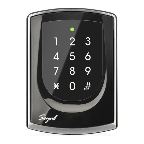
SOYAL
ACCESS CONTROL SYSTEM
Contents
AR-725 (E-V2-M)
1
Products
A.
B.
AR-725 (E-V2)
1
Products
A1.
E.
AR-725 (X)
1
Products
A2.
A3.
Parts Description
Button Head Pozidriv
a.
Tapping Screw: M3x10
d.
Security Torx Screw:
M3.5x15
Installation
AR-725 (E-V2-M)
3
A.
A.
2
C.
4
1
B.
c.
AR-725 (E-V2)
F.
1
AR-725 (X)
A1.
A3.
1
b.
G.
f.
®
2
C.
D.
2
User Guide
F.
B.
C.
G.
b.
e.
A.
B.
C.
B.
6
5
D.
F.
E.
A1.
2
3
4
e.
f.
5
A1.+A3.
H.
A2.
4
e.
AR-725 (E-V2)
User Guide
3
Terminal Cables
P4
3
Terminal Cables
P4
H.
D.
Button Head Pozidriv
Slotting Screw: 2.5x10
Flat Head Hex Socket
Screw: M3x8
Pull the cables from the square access hole of the mounting plate C.
Use a screwdriver to screw the metal plate C to the wall.
A.
7
Take off the plastic mounting plate B from the body A, and pull the cables
C.
through the access hole of C and B, then connect to the body A.
Assemble plate B with the body A, and embed the water proof strip D
onto the plastic side frame.
d.
8
Assemble the body A onto the mounting plate C with the Allen key and
g.
screws (accessories supplied).
Turn on the power and LED will light and beep will sound.
Use a screwdriver to screw the base F onto the wall.
Attach the water proof gasket to the body A1, and pull the cables
from the square hole of the base F, and connect to the body A1.
Assemble the body A1 with the base F.
Screw A1 and F tight with the Allen key and screws (accessories
supplied).
Turn on the power and LED will light and beep will sound.
Put on G, and attach A1 onto the plastic plate A3, and screw it with
the Allen key and screws (accessories supplied).
D.
Put the ring O on the metal frame, and put them together onto the
reader A1+A3, and screw them and buckle up the 4 buckles on the
back.
a.
Embed the water proof strip D onto the frame side of the base.
5
Following by the install process of AR-725 (E-V2-M).
4
Tools
P1
P2
P3
P5
P6
※
P7
4
Tools
P1
P2
P3
※
P7
P5
P6
2
Tools
a x2
b x2
c x2
Flat Head Cap Philips
c.
Tapping Screw: 4x19.1
V130116
c x2
d x1
e x2
d x1
Advertisement
Table of Contents

Related Manuals for Soyal AR-725


Summary of Contents for Soyal AR-725
- Page 1 Put the ring O on the metal frame, and put them together onto the reader A1+A3, and screw them and buckle up the 4 buckles on the back. Embed the water proof strip D onto the frame side of the base. Following by the install process of AR-725 (E-V2-M).
-
Page 2: Connector Table
Access controller Illuminated Touch-panel V130116 Notice 1. Tubing: The communication wires and power line should NOT be bound in the same conduit or tubing. 2. Cable selection: Use AWG 22-24 Shielded Twist Pair to avoid star wiring. Use CAT5 for TCP/IP connection. 3. - Page 3 SOYAL ® AR-725 (E-V2) V130116 ACCESS CONTROL SYSTEM Connect to Electric Strike Connect to Door Contact POWER POWER 12VDC 12VDC Electric Strike Alarm N.O. N.C. N.O. Door Contact Relay Outpot Module N.O. Controller Controller N.C. EXIT POWER POWER 12VDC Door Contact...
- Page 4 (NN=00~15); HHMMhhmm=Starting time to ending time; 7123456H= 7 days of week + Holiday (F= 0: disable; 1: enable)] [e.g.]AR-725 (E-V2) (without WG reader), to set second time zone which could be passed only at 9:30am to 4:20pm on Mon, Wed and Fri.
-
Page 5: Restoring Factory Settings
→ arming code → arming code → ※ Factory default armingcode is: 1234. U=Reader unit (0=AR-725 (E-V2), 1=WG Reader). Restoring Factory Settings Reset all device parameters and user card data Reset all device parameters and user card data: 29 9 Access programming mode →... - Page 6 Illuminated Touch-panel V130116 IP Setting Open your Web Browser and input factory default IP address: http://192.168.1.127 If the IP address of AR-725 (E-V2) has changed We must enter the new IP address. Page menu Monitor the on-line computer IP Setting...
-
Page 7: Command List
Exiting programming mode and enabling all device Including AR-725 (E-V2), WG Reader into arming status. Enabling each device into arming status. U=Enable target unit (0=AR-725 (E-V2) , 1=WG Reader) NNN=Node ID,(001~254) Node ID setting MMM=AR-725 (E-V2) Door Number,(001~255) AAA=WG Reader Door Number,(001~255) default value = 192.168.1.127... -
Page 8: Function Default Value
※0:Disable Networking/Stand-Alone Duress Function and Arming output setting 0:Wiegand output ※1: Arming and Duress RS-485 Networking/Stand-Alone 401RO16B:00 ※HOST: 01 LED: 10 PRN: 11 [e.g.]Setting AR-725 (E-V2) : Arming and Duress+PRN→(1x008)+(1x 048)=056 Access programming mode → 28 → setting is completed...
Need help?
Do you have a question about the AR-725 and is the answer not in the manual?
Questions and answers