Table of Contents
Advertisement
Quick Links
Model Numbers: Single Side Units: MQVL48NE2, MQVL48LPE2
Bay Peninsula Units: MQVLBG48NE2, MQVLBG48LPE2
ANSI Z21.88-2017/CSA 2.33-2017 and CSA2.17-2017
Certified to:
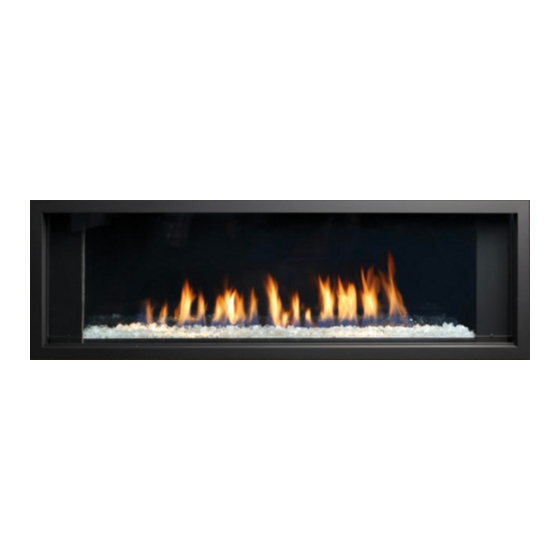
VENTED GAS FIREPLACE HEATER
- Certified for use with Adjustable Vented Platform (AVP), and Heat Distribution System (HDS) -
⚠
WARNING:
FIRE OR EXPLOSION HAZARD
Failure to follow safety warnings exactly could result in serious injury, death, or property damage.
-Do not store or use gasoline or other flammable vapors and liquids in the vicinity of this or any other
appliance.
-WHAT TO DO IF YOU SMELL GAS
• Do not try to light any appliance.
• Do not touch any electrical switch; do not use any phone in your building.
• Leave the building immediately.
• Immediately call your gas supplier from a neighbor's phone. Follow the gas supplier's
instructions.
• If you cannot reach your gas supplier, call the fire department
-Installation and service must be performed by a qualified installer, service agency or the gas
supplier.
INSTALLER: Leave this manual with the appliance.
This appliance may be installed in an aftermarket, permanently located, manufactured home (USA only) or mobile home,
where not prohibited by local codes.
This appliance is only for use with the type of gas indicated on the rating plate. This appliance is not convertible for use
with other gases, unless a certified kit is used.
- Installation Instructions -
⚠
WARNING: DO NOT OPERATE THIS APPLIANCE WITHOUT
DECORATIVE GLASS EMBERS ON BURNER AND MEDIA TRAY
VENTED GAS FIREPLACE HEATER:
NOT FOR USE WITH SOLID FUEL
Winnipeg, Manitoba Canada R2R 2V3 Ph.: (204) 632-1962
Printed in Canada July 11, 2022 Part# 48MQVLBG-MAN17
CONSUMER: Retain this manual for future reference.
A Division of R-Co. Inc. 2340 Logan Ave.
ENCLAVE
Advertisement
Table of Contents

Related Manuals for Kingsman Fireplaces marquis ENCLAVE MQVL48LPE2


Summary of Contents for Kingsman Fireplaces marquis ENCLAVE MQVL48LPE2
- Page 1 - Installation Instructions - Model Numbers: Single Side Units: MQVL48NE2, MQVL48LPE2 Bay Peninsula Units: MQVLBG48NE2, MQVLBG48LPE2 ENCLAVE ANSI Z21.88-2017/CSA 2.33-2017 and CSA2.17-2017 Certified to: VENTED GAS FIREPLACE HEATER - Certified for use with Adjustable Vented Platform (AVP), and Heat Distribution System (HDS) - ⚠...
- Page 2 IT IS THE RESPONSIBILITY OF THE HOME OWNER TO ENSURE THAT NO ONE TOUCHES A HOT APPLIANCE. • If the barrier becomes damaged, the barrier shall be replaced with the manufacturer’s barrier for this appliance. • Any safety screen, guard, or barrier removed for servicing the appliance, must be replaced prior to operating the...
-
Page 3: Table Of Contents
MQVL48 / MQVLBG48 Table of Contents Table of Contents............................Warnings................................ Installation Requirements for the Commonwealth of Massachusetts............Carbon Monoxide (CO) Detector........................Pre-installation Questions and Answers......................Operations and Maintenance Instructions...................... Mobile Home/Manufactured Housing Installation................... Fireplace Installations in Covered Outdoor Locations..................Installation & Framing Framing Your Gas Fireplace.......................... - Page 4 MQ Dealer Accessories - MQVL48 / MQVLBG48..................48-49 MQRBD3 - 5 Pc. Driftwood Log Set....................... MQLOGF48D - 6 Pc. Driftwood Log Set......................MQRBRW – 5 Pc. Birchwood Log Set......................Burner System Gas Line Installation / Gas Specifications Chart.................... Annual Inspection List............................ Troubleshooting the Gas Control System......................
-
Page 5: Warnings
Warnings, Installations and Operations - Installation Regulations This gas appliance must be installed by a qualified installer in accordance with local building codes, or in the absence of local codes, with the current CAN/CSA-B149.1 or .2 Installation Code (in Canada) or the current National Fuel Gas Code Z223.1- NFPA 54 when installed in the United States. -
Page 6: Installation Requirements For The Commonwealth Of Massachusetts
Installation Requirements for the Commonwealth of Massachusetts In the Commonwealth of Massachusetts, the installer or service agent shall be a plumber or gas fitter licensed by the Commonwealth. When installed in the Commonwealth of Massachusetts or where applicable codes; the unit shall be installed with a CO detector per the requirements listed below. -
Page 7: Pre-Installation Questions And Answers
Pre-installation Questions and Answers About curing of the paint Your stove or fireplace has been painted with the highest quality silicone stove paint. This paint dries quickly in 15-20 minutes when first applied at the factory. However, due to the high temperature silicone components, the paint will cure when heat is applied to the appliance as it is first used. -
Page 8: Mobile Home/Manufactured Housing Installation
Mobile Home/Manufactured Housing Installation This Direct Vent System Appliance must be installed in accordance with the manufacturer’s installation instructions and the Manufactured Home Construction and Safety Standard Title 24 CFR, Part 3280, or the current Standard for Fire Safety Criteria for Manufactured Home Installations, Sites, and Communities ANSI/NFPA 501A, and with CAN/CSA Z240 MH Mobile Home Standard in Canada. -
Page 9: Fireplace Installations In Covered Outdoor Locations
Fireplace Installations in Covered Outdoor Locations – FOR BASIC MILLIVOLT UNITS ONLY- NO FAN – NO LIGHTS- CAUTION – Installation of an indoor gas fireplace with an outdoor exposure is not covered under the (ANSI Z21.88 – CSA 2.22 or ANSI Z21.50 – CSA 2.33) standard(s) used to certify the indoor gas-fired fireplace. The Intertek safety certification will not apply to this installation method. -
Page 10: Framing Your Gas Fireplace
Framing Your Gas Fireplace This section is intended for qualified installers only. Before beginning, make note of where the gas and electrical accesses are located on the unit. This will streamline the construction process. Furthermore, familiarize yourself with the venting and clearance requirements (see Venting section) for this appliance. -
Page 11: Vented Chase Requirements
MQVL48 / MQVLBG48 -Vented Chase Requirements FIREPLACE CHASE MUST BE VENTED AT TOP AND BOTTOM- Minimum Chase Vent Openings LARGER than the required minimums ARE allowed square inches free air opening at the top of the chase, and minimum square inches free air opening at the bottom of the chase. -
Page 12: Vl48Avp Adjustable Vented Platform
Adjustable Vented Platform VL48AVP, VL60AVP, VL72AVP -Option The Adjustable Vented Platform is an IMPORTANT NOTES: optional installation base. Height is AVP SHOULD BE IN PLACE AND LEVEL BEFORE UNIT IS INSTALLED. ATTACH FIREPLACE TO AVP WITH SCREWS PROVIDED. variable from approximately 15”... - Page 13 STEP ONE: ASSEMBLE BASE REAR BRACE SELF- OUTER CLINCHING OUTER SIDE STUD SIDE PANEL PANEL INNER FRONT PANEL 1. Assemble Base of Platform using supplied self-clinching OUTER SIDE studs, nuts, and screws. OUTER PANEL SIDE PANEL SELF- CLINCHING STUD OUTER OUTER SIDE SIDE...
-
Page 14: Mqvl48 / Mqvlbg48 Framing - Platform Base
MQVL48 / MQVLBG48 Framing – Platform Base A Platform Base has air opening requirements that must be met. Top of Platform Must Have Minimum Square Inches Free Air Opening ⚠ DO NOT COVER TOP OF PLATFORM Front Must Have Square Minimum Inches Free Air Opening EXAMPLE: 2”... -
Page 15: Vl48Eg Grill Installation
VL48EG Grill Installation- -Option- Compatible with both Vented Chase and HDS ⚠ Grill openings must be within 2” of enclosure top. This is to prevent excess heat from becoming trapped in the top of the chase. See installation section of manual. Parts List: [1] Louver Grill (ready to paint) This Grill Meets Minimum Opening Air Free Requirements. -
Page 16: Vl60Egs Side Grill
VL60EGS Side Grill Installation - MQVL48, MQVLBG48 Option Not compatible with HDS System. ⚠ Grill openings must be within 2” of enclosure top. Contents of Kit: [Qty 2] Side Grill assemblies (ready to paint). This is to prevent excess heat from becoming trapped in the top of the chase. -
Page 17: Vl48Hds Optional Heat Distribution System
VL48HDS Optional Heat Distribution System -Option *Requires ZDV5FP6 Flex Pipe Kit (Contains 4 pcs. 5”diameter flex pipe 6’ long). Uses Kingsman VL48EG Grill Must be installed before front framing is in place. Minimum 151 Sq. In. Free Air Equivalent Plenum Connect only the two center pipes when venting to an optional secondary vent opening. -
Page 18: Tile Lip Kit - 48Vl-Tlk
48VL-TLK Tile Lip Kit - Optional The 48VL-TLK Kit may be used as a trim around the opening of the fireplace. Fasten with supplied self-tapping screws. ITEM PART QUANTITY DESCRIPTION NUMBER NUMBER Kit Consists of items 1-4 48VLBG-TLK1 Front Bottom Tile Lip 56-3/16” 48VLBG-TLK2 Side Horizontal Tile Lip 16-1/4”... -
Page 19: Clearance To Combustibles
MQVL48 / MQVLBG48 Clearance to Combustibles Front (Furniture, etc. from glass) 36” [92cm] Side (Furniture, etc. from glass) 8-1/2” [21.6cm] ⚠ NOTE If using insulation in vented Side (from Stand-offs of VLBG48 or Corner Kit) 0” [0cm] chase (i.e. for outside wall), Back (from Stand-offs) 0”... -
Page 20: Mantel Clearances / Adjacent Wall
MQVL48 / MQVLBG48 Mantel Clearances SIDE VIEW (MQVLBG48 Shown) A Combustible Mantel 151 sq. can be placed immediately in. Min. above the fireplace 1 in. Min. 3/4” opening. A Combustible Hearth can be placed immediately 28-1/2” below the fireplace (55” TV) opening. -
Page 21: Mqvl48 Single Side Locating Your Appliance
MQVL48 Single Side Locating Your Appliance LOCATION KEY: Left Side Corner Flat on Wall 45° Corner As a Room Divider As an Island* Right Side Corner Exterior Wall Chase 20’ MAX *Island installation with a top vent is possible as long as the horizontal portion of the vent system does not 20’... -
Page 22: Nailing Tab Guide
MQVL48 Single Side -Nailing Tab Guide- [Qty] 4 Nailing Tabs are located on each side of the front frame. NOTE: If using the rear nailing tabs for cantilevered chase etc., refer to the Nailing Tab page for MQVLBG48 Bay Peninsula. Pull up 90°... -
Page 23: Single Side Framing
MQVL48 Single Side Framing TOP VIEW Stud Stud BACK WALL FRAMING MQVL48 Single Side Units- No Framing on Top Sides of fireplace 19” Framing Flush with Face FRAMING OVER FRONT TOP OF FIREPLACE FRAMING FRONT FIREPLACE FRAMING IN FRONT OF FIREPLACE Variable –... -
Page 24: Facing Requirements
MQVL48 – Single Side -Facing Requirements Unit may be covered with combustible material (i.e. drywall) up to the fireplace opening. NOTE: If installing VL48S1BL or SS Surround: 5/8” Space is required around fireplace opening. Do not allow wall covering to come within this area. Option A: Open Chase at Ceiling (MIN Sq. -
Page 25: Vl48S1Bl / Vl48S1Ss -Surround Installation For Mqvl48
VL48S1BL / VL48S1SS -Surround Installation for MQVL48 -Option NOTE: Install before applying the PARTS LIST: finishing materials. Install Tile Lip - [Qty 1] Surround Frame (supplied with fireplace) using second - [Qty 2] Black Side Fillers hole from top, as shown. This will provide - [Qty 1] Bottom Filler the required 5/8”... - Page 26 INSTALLATION: - Fireplace must be installed and wall surface must be finished. -Insert assembled Surround into fireplace opening. [Qty 4] Surround Tabs will fit into [Qty 4] Fireplace Slots. Surround Tabs -Insert [Qty 4] screws through the holes in the Surround Tabs and into the Fireplace.
-
Page 27: Mqvl48Sep Side Extension Panels
MQVL48 Single Side- VL48SEP Side Extension Panels -Option- Contents if Kit: Qty 2 – Side Extension Panels Qty 4 - #6 Black Screws 4” 18-3/16” 19-7/16” Framing Details: FROM EDGE OF FIREPLACE TO OUTSIDE OF 2 X 4 HORIZONTAL FRAMING ABOVE TOP OF 19-3/16”... -
Page 28: Glass Front Removal / Installation
MQVL 48/60/72 Single Sided Units- -Glass Front Removal / Installation- To remove Glass Front: 1. Remove Wing Nuts on the Upper Glass Retainer above the Glass Door Front and remove the Retainer. 2. Loosen Wing Nuts on the Lower Glass Retainer but do not remove. 3. -
Page 29: Locating Your Appliance
MQVLBG48 Bay Peninsula Locating Your Appliance LOCATION KEY: A. Corner Kit- Left Side B. Flat on Wall C. Corner Kit- Right Side D. Corner Kit- Left Side E. Corner Kit- Right Side F. 45° Corner G. As an Island* *Island installation with a top 20’... -
Page 30: Bay Peninsula Framing
MQVLBG48 Bay Peninsula -Framing OPTION A: Framing Attached to Side of Fireplace- For building out around the fireplace. NOTE: Appliance and framing structures are not load bearing. RIGHT SIDE VIEW -TOP VIEW- BACK WALL 19” MIN FRAMING ON TOP OF FIREPLACE VARIABLE Can be built out to desired... -
Page 31: Bay Peninsula Nailing Tabs And Framing
MQVLBG48 Peninsula –Nailing Tabs and Framing OPTION A: Framing Attached to Side of Fireplace- For building out around the fireplace. Framing must be self- supporting. SIDE NAILING TAB Optional framing attached to side MIN. 151 of fireplace SQ. IN. Example: 48-5/8”... -
Page 32: Vlbgck Corner Kit
VLBGCK - Corner Kit - for MQVLBG48/60/72 Peninsula Bay Option - MUST BE INSTALLED BEFORE ⚠ Warning: Failure to position the parts in accordance with UNIT IS INSTALLED INTO FRAMING. these diagrams or failure to use only parts specifically - CORNER KIT CAN BE INSTALLED approved with this appliance may result in property damage AT EITHER END OF FIREPLACE. - Page 33 STEP TWO: INSTALL FIREBOX COVER A. Apply a 3/8” bead of Mill- Pac onto the Seal Seal Gasket Gasket of the Firebox 3/8” Bead Cover. Do not Apply Mill- of Mill-Pac Pac onto the Front Glass Gasket. See Photo. B. Insert Firebox Cover Front Glass through front of fireplace Gasket...
- Page 34 G. Install Inner Liner Panel inside of Firebox. Use [Qty 7] DT Screws to attach top, bottom, and Install Inner STEP FOUR: INSTALL back of Liner Panel Fireplace Outer FIREPLACE OUTER COVER inside of Cover H. Use the [6] Pan Head firebox Screws supplied along front edge of Fireplace...
-
Page 35: Mqvlbg48 Bay Peninsula
MQVLBG48 Bay Peninsula -Facing Requirements Unit may be covered with combustible material (i.e. drywall) up to the fireplace opening. Option A: Open Chase at Ceiling Minimum 151 Sq. Inches. Option B: Vent Slot in Chase MAX 2” Below Ceiling Minimum 151 Sq. Inches. Do not drive screws into fireplace front. -
Page 36: Front Glass Installation / Removal
MQVLBG 48/60/72 Bay Peninsula Units- - Front Glass Installation and Removal - SILICONE SILICONE ALIGNMENT ⚠ IMPORTANT: Each corner must have a dab of high-temp silicone placed between the ball of the gasket and the corner glass. This will fully seal the firebox corners. Front Glass is placed in front of corner glass edge. -
Page 37: Side Glass Door Installation / Removal
Enclave Series 48/60/72 – Bay Peninsula Units- – Side Glass Removal and Installation Remove Front Firebox Glass first. If the Side Glass ⚠ IMPORTANT: Front corners must have a dab of high- Panel or another component must be cleaned or temp silicone placed between the ball of the gasket and replaced, remove the 4 Wing Nuts from the Side Glass Door and remove Retainers, Glass Door Frame, and... -
Page 38: Door And Glass Information
Door and Glass Information MQVL48 / MQVLBG48 Glass Cleaning It will be necessary to clean the glass periodically. During startup, condensation, which is normal, forms on the inside of the glass, and causes dust, lint etc. to cling to the glass surface. Also, initial paint curing can deposit a slight film on the glass. -
Page 39: Mqvl48 / Mqvlbg48- Glass Safety Barrier Installation / Removal
MQVL48 / MQVLBG48– Glass Safety Barrier Installation / Removal INSTALL SIDE GLASS FIRST. DECAL ON GLASS SHOULD FACE OUTSIDE. 16-3/16” 16-3/16” 54-5/8” 14-3/8” FRONT GLASS PANEL [QTY 1] SIDE GLASS PANELS [QTY 2] GLASS SUPPORTS PLACE GLASS INTO GLASS INSERT GLASS INTO CLIPS IN TOP OF FIREPLACE SUPPORTS. -
Page 40: Component Locations
MQVL48 / MQVLBG48 Component Locations TOP VIEW GAS LINE LIGHT 120 VAC 120 VAC VALVE OPTIONAL DRIVER MODULE BATTERY REMOTE PAIRING BUTTON (LED) BACKUP (SW1 SWITCH) REMOTE PAIRING BUTTON (SW1 SWITCH) -
Page 41: Led Lighting
MQVL48 / MQVLBG48 LED Lighting Please follow the current ANSI/NFPA 70 National Electrical Code in the USA and CAN/CSA C22.1 Canadian National Electrical Code in Canada. LED Light Strip is Located Under the Firebox. LED LIGHT STRIP 584-X10 HARNESS YELLOW CONNECTOR GROUNDING STUD PROFLAME 2 MODULE LED CONTROLLER... -
Page 42: Vl48Plb / Vl48Ple Porcelain Liner Installation
VL48PLB / VL48PLE Porcelain Liner Installation Option -VL48PLB- BACK PANEL KIT NOTE: If using VLBGCK CORNER KIT, DO NOT USE BACK FILLER Inner Liner Panel from Corner Kit. Remove if installed. STEP ONE: Remove Liner Clips and screws from inside of firebox with a BACK LINER 1/4”... -
Page 43: Mqvl48Rgb Glass Back Liner Installation
MQVL48RGB Glass Back Liner Installation Option MQVL48RGB - BACK PANEL KIT STEP ONE: Remove Liner Clip and screws from inside of firebox with a 1/4” hex NOTE: Install CONTENTS: driver. Discard Back Clip MQVL48RGB Before GLASS BACK but Keep Screws. installing LINER X 3 MQVL48RGE... -
Page 44: Mqvl48Rge Glass End Panel Installation
MQVL48RGE Glass End Panel Installation Option -MQVL48RGE - END PANEL KIT ⚠ CAUTION – NOT TEMPERED GLASS- EXTREMELY FRAGILE – HANDLE WITH CARE RIGHT NOTE: Back Glass Liners must be installed first. LEFT SIDE SIDE GLASS GLASS NOTE: If using VLBGCK CORNER KIT and you are NOT installing PANEL PANEL a Glass End Panel, install Inner Liner Panel from Corner Kit before... - Page 45 STEP THREE: Engage Front Slot of Tab with DT Screw in side wall of firebox. There is no bottom attachment Screw. FRONT FIREBOX LEFT SIDE END PANEL Repeat actions for other side. NOTE: if you are using VLBGCK CORNER KIT, only one End Panel will be used. ⚠...
-
Page 46: Mqvl48Rlsb / Mqvl48Rlse Liner Installation
MQVL48RLSB / MQVL48RLSE Stacked Brick Liner Installation Option MQVL48RLFB / MQVL48RLFE Fluted Liner Installation Option -MQVL48RLSB- BACK LINER KIT STEP ONE: Prepare the fireplace. BACK LINER Remove Upper Liner Clips from inside of firebox with a 1/4” hex driver. Liners are Identical No Left or Right... - Page 47 STEP FOUR: Install Lower Liner Clips [x4]. LOWER LINER CLIP X 4 LOWER LINER CLIP (X4) MEDIA TRAY STEP FIVE: Install Side Liners. Reinstall End Clips with DT Screws. See Step Five Reference Drawing on Previous Page. NOTE: If using VLBGCK CORNER KIT, remove Inner Liner Panel from Corner Kit if installed. ⚠...
-
Page 48: Mq Dealer Accessories - Mqvl48 / Mqvlbg48
MQVL48 / MQVLBG48 MQ Dealer Accessories The following Accessories are available through MQ Dealers only. CRUSHED GLASS MEDIA ACCESSORY ITEM DESCRIPTION Spread the glass embers onto the false bottom and burner. MQG5C Ensure the glass embers do not excessively overlap as this will affect Decorative Ember Glass –Bronze the flame pattern. - Page 49 MQROCK2, MQROCK3, MQRBD1 - Place rocks randomly onto False Bottom. MQRock2 MQRock3 MQRBD1 NOTE Pilot Area Must Not Be Covered, as delayed ignition can occur. Do Not Cover any part of the burner tube with logs as sooting may occur. ...
-
Page 50: Mqrbd3 - 5 Pc. Driftwood Log Set
MQRBD3 -5 Piece Driftwood Log Set- Can be used with MQ Glass, MQ Rock, MQ Stone or MQ Ember. Follow instructions for these accessories. ⚠ NOTE LOG 1 For best flame pattern it LOG 3 is essential to spread supplied Crushed Glass or MQEMBER directly LOG 4... -
Page 51: Mqlogf48D - 6 Pc. Driftwood Log Set
Enclave Series MQLOGF48D OPTION Can be used with MQ Glass, MQ Rock, MQ Stone or MQ Ember. Follow instructions for these accessories Enclave Series MQRBRW OPTION ⚠ NOTE • Pilot area must not be covered, as delayed ignition could occur •... -
Page 52: Gas Line Installation / Gas Specifications Chart
MQVL48 / MQVLBG48 Gas Line Installation This gas appliance should be installed by a qualified installer in accordance with local building codes and with current CAN/CGA - B149.1 or .2 installation codes for Gas Burning appliances and equipment in Canada and the National Fuel Gas Code ANSI Z223 in the U.S.A. -
Page 53: Annual Inspection List
Annual Inspection List for Determining Safe Operation of a Direct Vent Gas Fireplace Refer to this checklist for proper maintenance, safe use, and operation. See each section for more specific information. 1. Inspect and operate all pressure relief mechanisms (i.e., relief dampers, spring loaded door latches) installed on your appliance to verify relief mechanisms are free from obstruction to operate. -
Page 54: Troubleshooting The Gas Control System
Troubleshooting the Gas Control System ⚠ WARNING BEFORE DOING ANY GAS CONTROL SERVICE WORK, REMOVE THE GLASS FRONT. NOTE: Before troubleshooting the gas control system, be sure external gas shut off is in the "On" position. Problem Possible Causes Corrective Action Spark igniter will not Defective or misaligned Check for spark at electrode and pilot: if no spark and electrode wire is... -
Page 55: Burner System Maintenance
Burner System Maintenance MQVL48 / MQVLBG48 It is recommended to annually inspect and clean the Burner System to prevent malfunction and / or sooting. This operation should be performed by your dealer or a qualified technician. ⚠ -CAUTION- Before servicing the burner system ensure that the gas supply is turned OFF and disconnect all electrical connections to the appliance. -
Page 56: Gas Conversion Part A
-Gas Conversion Part A- MQVL48 / MQVLBG48 Models: MQVL48NE2, MQVL48LPE2, MQVLBG48NE2, MQVLBG48LPE2 Kit Number Description Pilot Orifice Burner Orifice Brass Nipple Air Shutter Hi/Lo Regulator Brass (1000-255) 48VL-CKLPI2 Propane Conversion 1001-P168SI 1000-253 1002-P012SI Fully Open #35 (977.168) -IPI- Closed (907.012) 48VL-CKNGI2 NG Conversion 1001-P166SI... -
Page 57: Gas Conversion For Top Convertible Pilot - Part B
Gas Conversion for Top Convertible Pilot – Part B (series 0190XYZ) Instructions for converting SIT 190 series pilot burner injector from NG to PROPANE and from PROPANE to NG only. This information should be considered as supplemental to the Appliance Manufacturer's Instructions. -
Page 58: Gas Conversion For Modulator - Part C
Gas Conversion for Modulator – PART C... -
Page 59: False Bottom Removal (Media Tray)
MQVL48 / MQVLBG48 False Bottom Removal (Media Tray) In order to access the Burner Tube and Burner Pan, the False Bottom must be removed. STEP 1:MQVLBG48 Units Remove Retainers from STEP 2: Remove the [Qty 8] Screws shown below. each end of False Bottom. False Bottom can now be removed from fireplace. -
Page 60: Electronic Ignition Lighting Instructions
- IPI LIGHTING INSTRUCTIONS - FOR YOUR SAFETY READ BEFORE LIGHTING WARNING: If you do not follow these instructions exactly, a fire or explosion may result causing property damage, personal injury or loss of life. • This appliance is equipped with an ignition device which If you cannot reach your gas supplier, call the fire automatically lights the pilot. -
Page 61: Proflame 2 Parts List
Proflame 2 –NE2 / LPE2 -IPI System Parts List- IPI PROFLAME 2 - COMPONENT PARTS IPI - PF1 and PF2 Common Components PART NO. DESCRIPTION PART NO. DESCRIPTION 1005-P001SI Valve IPI Proflame PF2 885.001 NG - Stepper 13. 1002-P033SI TC - Pilot Burner IPI (Assembled) NG 199.033 1005-P002SI Valve IPI Proflame PF2 885.002 LP - Stepper 14. -
Page 62: Proflame 2 Module And Remote Control
Proflame 2 Module and Remote Control PRESS BUTTON REMOTE PAIRING BUTTON (SW1 Switch) Two Remote Control Models: Batteries Batteries Pairing Remote Control Install the 3 AAA batteries in the battery bay, located on the • Press the SW1 button until you hear three beeps. •... -
Page 63: Cold Climates - Cpi Setting - Proflame 2 Remote Control
Cold Climates – CPI Setting - Proflame 2 Remote Control Use the CPI setting during cold weather, otherwise the fireplace may have a hard time starting up and establishing a flame. The CPI (Continuous Pilot Ignition) setting will keep the firebox and fireplace exhaust vent warm during cold weather. -
Page 64: Proflame 2 Remote Control Operation
Proflame 2 Remote Control... - Page 65 Note: When Smart Thermostat is activated, manual flame height adjustment is disabled. (Halogen lights only) Note: This function is only available in Room Thermostat or Smart Thermostat Control Mode.
-
Page 67: Vent Terminal Clearances
Vent Terminal Clearances NOTE: A HORIZONTAL VENT CERTIFIED GUARD (SAFETY CAGE) IS AVAILABLE WHEN REQUIRED BY LOCAL CODES. Clearances are to the edge of the terminal plate. Add 6-3/4” to clearances to arrive at centerline. Local codes or regulations may require different clearances. -
Page 68: General Vent Installation
General Vent Installation Information This gas appliance is approved to be vented either through Place the spring spaces provided approximately every two the side wall or vertically through the roof. Only Kingsman feet to stabilize 5” flex in the center of 8” flex. When forming Flex (Z-Flex) Venting Kits and components specifically bends place spring in bend or before and after. -
Page 69: Installation Of Side Wall Venting
MQVL48 / MQVLBG48 Installation of Side Wall Venting To determine the minimum distance from the bottom of fireplace to center of vent see the Framing Your Gas Fireplace section. Cut a hole through the wall allowing for a 12” x 12” (inside diameter) in combustible walls for wall thimble or a 9” diameter hole in a non-combustible wall (See Figure 2). -
Page 70: Venting Routes And Components
Venting Routes And Components Venting Routes and Components How to Use the Horizontal Vent Table Since it is very important that the vent system maintain its 1. Determine the height of the system and the number of balance between the combustion air intake and the flue gas bends required. -
Page 71: Flue Restrictor
Enclave Series VL / VLBG 48 / 60 / 72 Flue Restrictor The Flue Restrictor is located in the top of the Firebox in front of the Flue Opening. For power vent and longer vertically vented installations it may be necessary to use the Flue Restrictor. The Flue Restrictor is set fully open from the factory for short horizontal and vertical runs. -
Page 72: Venting Straight Up Through Roof
Venting Straight Up Through Roof An Attic Insulation Shield must be installed where the vent passes from a lower living space into an attic space where the chimney is not enclosed. It is designed to keep insulation materials away from the chimney. When installing the Attic Insulation Shield where the chimney passes from a living space to an attic space, install the shield from below and nail in place using 1"... - Page 73 -Restrictor- Remove for Runs Under 15 Feet Clearances in horizontal venting. Z58VT Clearance to perpendicular wall 24 inches (60 cm). (Recommended to prevent re- circulation of exhaust products. For additional requirements check local codes.) 24” 18” MIN Clearance above highest point of exit on roof 18 inches (45cm) 43ft...
-
Page 74: Cathedral Ceilings
Enclave Series Venting - Cathedral Ceilings Just as with a normal ceiling, an Attic Insulation Shield must be WARNING: HEAT CANNOT BE DISCHARGED installed where the fireplace vent passes from a lower living space into INTO THE WALLS, FLOOR, OR CEILING. Heat an attic space when installing a fireplace into a room with a cathedral must exit through the required size of opening at the top of the chase. -
Page 75: Approved For Power Vent
Approved for Power Vent PVH58 / PVH58FM - This appliance is approved for use with Kingsman Horizontal Power Vents - A Horizontal Power Vent Termination is intended for use where standard venting configurations are not possible. NOTE: MODELS EQUIPPPED WITH MILLIVOLT/ STANDING PILOT IGNITION: Downward vertical vent runs are NOT permitted. -
Page 76: Pvh58 Parts List
Power Vent Parts List – 5/8 Venting NUMBER DESCRIPTION PVH58 Horizontal Power Vent Starter Kit ‐ Exterior Mount PVH58FM Horizontal Power Vent Kit ‐ Flush Mount Note: Must use a one foot section of 5/8 DV hard pipe to connect to the Power Vent Termination (not supplied) CHOOSE CONTROL MODULE OR HARNESS DEPENDENT ON VALVE SYSTEM PVC58MV Power Vent Control Module ‐... -
Page 77: Mqvl48 / Mqvlbg48 Parts List
MQVL48 / MQVLBG48 - Parts List - Part No. Description Single Side Fireplaces MQVL48 / MQVL48B Media Options WARNING: DO NOT OPERATE THIS APPLIANCE MQVL48NE2 Heater Rated Fireplace, NG, WITHOUT DECORATIVE GLASS EMBERS ON Ceramic Glass, Low E Tempered BURNER AND MEDIA TRAY Glass Safety Barrier, IPI System 2, RBCB1 Cannonballs- Assorted size and... - Page 78 Z58FK5 Flex Kit (5” & 8” Dia.) x 2.5’ Firebox Glass & Gasket (Unexpanded) 48VLBG-310 Ceramic Glass - 49 1/16 x 17 7/8 - 5’ Expanded Rev A - No Gasket Required – Z58FK8 Flex Kit (5” & 8” Dia.) x 4’ For MQVLBG48 (Unexpanded) 48VLBG-310SS...
-
Page 79: Limited Lifetime Warranty
This Limited Lifetime Warranty applies only while the unit remains at the site of the original installation and only if the unit is installed inside the continental United States, Alaska, Hawaii, and Canada. The warranty applies only if the unit is installed and operated in accordance with the printed instructions and in compliance with applicable installation and building codes and good trade practices.
Need help?
Do you have a question about the marquis ENCLAVE MQVL48LPE2 and is the answer not in the manual?
Questions and answers