Table of Contents
Advertisement
Quick Links
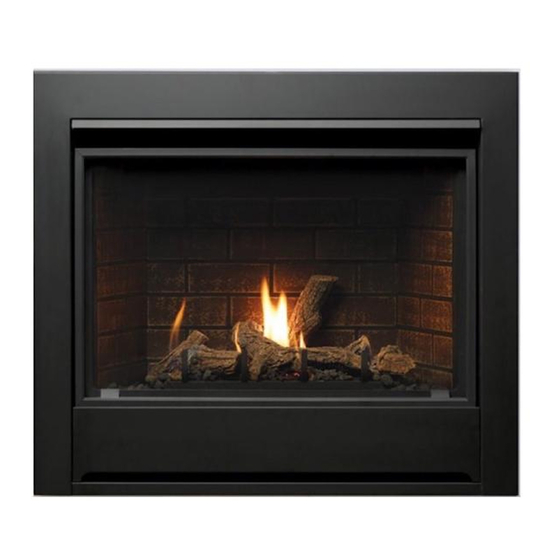
Solara Installation Instructions
Model
MQZDV3318N, MQZDV3318NE, MQZDV3318NE2, MQZDV3318LP, MQZDV3318LPE,
Numbers:
MQZDV3318LPE2
ANSI Z21.88-2017 • CSA 2.33-2017 Vented Gas Fireplace Heaters, CSA 2.17-2017
Certified to:
MQZDV3318
This appliance may be installed in an aftermarket,
permanently located, manufactured home (USA
only) or mobile home, where not prohibited by
local codes.
This appliance is only for use with the type of
gas indicated on the rating plate. This appliance
is not convertible for use with other gases,
unless a certified kit is used.
INSTALLER: Leave this manual with the appliance.
CONSUMER: Retain this manual for future reference.
A Division of R-Co. Inc.
2340 Logan Ave.
Winnipeg, Manitoba Canada
R2R 2V3 Ph.: (204) 632-1962
Printed in Canada December 14, 2021
Part# 3318MQ-MAN17
Advertisement
Table of Contents

Related Manuals for Kingsman Fireplaces Marquis MQZDV3318


Summary of Contents for Kingsman Fireplaces Marquis MQZDV3318
-
Page 1: Cover
Solara Installation Instructions Model MQZDV3318N, MQZDV3318NE, MQZDV3318NE2, MQZDV3318LP, MQZDV3318LPE, Numbers: MQZDV3318LPE2 ANSI Z21.88-2017 • CSA 2.33-2017 Vented Gas Fireplace Heaters, CSA 2.17-2017 Certified to: MQZDV3318 This appliance may be installed in an aftermarket, permanently located, manufactured home (USA only) or mobile home, where not prohibited by local codes. -
Page 2: Table Of Contents
Table of Contents Cover..................................Table of Contents..............................Pre-installation Questions and Answers / Operations and Maintenance Instructions..........Safety Screen Installation............................Warnings, Installations and Operations - Installation Regulations................Installation Requirements for the Commonwealth of Massachusetts / Carbon Monoxide (CO) Detector....Mobile Home/Manufactured Housing Installation....................Recommendations for Finishing of Clean View Linear Products………………………………………………………... - Page 3 Venting Vent Terminal Clearances............................General Vent Installation ............................Installation Of Side Wall Venting………………………………………………………………………………………….. Venting Routes and Components / Horizontal Venting Table From Bottom of Fireplace........Z47ST24 / Z47ST36 Horizontal Snorkel Terminations................... Venting Straight Up Through Roof………………………………………………………………………………………... 55-56 Vertical Venting over 15 Feet..........................Glass Safety / Termination Cap Safety........................
-
Page 4: Pre-Installation Questions And Answers / Operations And Maintenance Instructions
Pre-installation Questions and Answers About curing of the paint Your stove or fireplace has been painted with the highest quality silicone stove paint. This paint dries quickly in 15-20 minutes when first applied at the factory. However, due to the high temperature silicone components, the paint will cure when heat is applied to the appliance as it is first used. -
Page 5: Safety Screen Installation
Safety Screen Installation Z Series Contents of Kit: [1] Safety Screen [2] Side Angles [2] Horizontal Angles [12-16] DT Screws (Depending on screen size) Assembly: Attach components with supplied screws as shown. NOTE: Screens are symmetrical from top to bottom. ⚠... -
Page 6: Warnings, Installations And Operations - Installation Regulations
Warnings, Installations and Operations - Installation Regulations This gas appliance must be installed by a qualified installer in accordance with local building codes, or in the absence of local codes, with the current CAN/CSA-B149.1 or .2 Installation Code (in Canada) or the current National Fuel Gas Code Z223.1- NFPA 54 when installed in the United States. -
Page 7: Installation Requirements For The Commonwealth Of Massachusetts / Carbon Monoxide (Co) Detector
Installation Requirements for the Commonwealth of Massachusetts In the Commonwealth of Massachusetts, the installer or service agent shall be a plumber or gas fitter licensed by the Commonwealth. When installed in the Commonwealth of Massachusetts or where applicable codes; the unit shall be installed with a CO detector per the requirements listed below. -
Page 8: Mobile Home/Manufactured Housing Installation
Mobile Home/Manufactured Housing Installation This Direct Vent System Appliance must be installed in accordance with the manufacturer’s installation instructions and the Manufactured Home Construction and Safety Standard Title 24 CFR, Part 3280, or the current Standard for Fire Safety Criteria for Manufactured Home Installations, Sites, and Communities ANSI/NFPA 501A, and with CAN/CSA Z240 MH Mobile Home Standard in Canada. -
Page 9: Recommendations For Finishing Of Clean View Linear Products
Recommendations for Finishing of Clean View Linear Products When finishing the wall around the fireplace, it is critical that the wall covering be fastened properly. It is acceptable to pre-drill holes and use self-tapping screws which may be used to fasten a backer for tile, marble, etc. Screws being installed through non-combustible board should be self-tapping type with a maximum length of 2 inches. -
Page 10: Fireplace Installations In Covered Outdoor Locations
Fireplace Installations in Covered Outdoor Locations – FOR BASIC MILLIVOLT UNITS ONLY- NO FAN – NO LIGHTS- CAUTION – Installation of an indoor gas fireplace with an outdoor exposure is not covered under the (ANSI Z21.88 – CSA 2.22 or ANSI Z21.50 – CSA 2.33) standard(s) used to certify the indoor gas-fired fireplace. The Intertek safety certification will not apply to this installation method. -
Page 11: Installation & Framing - Zdv3318Mq Locating Your Appliance / Fireplace Dimensions
MQZDV3318 - Locating your Appliance Installing with Top Vent A - Flat on a wall D - As a room divider B - Across the corner E - Flat on wall corner C - As an island F - Exterior wall Island installation with a top vent is possible as long as the horizon- tal portion of the vent system does not exceed 20 feet (6.1 m). -
Page 12: Framing Your Gas Fireplace
MQZDV3318 - Framing for your Gas Fireplace 4. When installing horizontal with a 90 degree bend maintain a Framing Specifications minimum of two and a half (2.5”) inches above the bend in 1. Cold climate installation recommendation: When installing this fire- enclosures. -
Page 13: Z33Cvck - Framing And Facing Requirements
Z33CVCK - Framing and Facing Requirements MQZDV3318 WITH Z33CVCK (CLEAN VIEW CIRCULATING KIT) Z33CVCK - with Wall Surround... -
Page 14: How To Install Clean View Kit (Cvck)
How To Install Clean View Kit (CVCK) For ZDV3318 / ZDV3622 / ZDVRB3622 / ZDV6000 / ZDV3320 / MQRB3328 / MQZDV3318 / MQZDV3622 WARNING: Failure to position the parts in accordance with these diagrams or failure to use only parts specifically approved with this appliance may result in property damage or personal injury. -
Page 15: Clearances - Mantels & Surrounds
CLEARANCES - MQZDV3318/3622 - Mantels & Surrounds Warning: Combustible objects must not be placed on a non-combustible mantel unless the non-combustible mantel meets the minimum height and width require ments for a combustible mantel. -
Page 16: Mantel Leg Clearances
Mantel Leg Clearances Mantels Depending on the depth of the fireplace mantel, it may be installed higher or lower from the top of the fireplace opening. See drawings for proper installation height of your combustible mantel. Non-combustible mantels may be installed at any height above the fireplace opening except when using MQHBSW. -
Page 17: Clearance To Combustibles
ZDV3318 / MQZDV3318 - Clearance to Combustibles Clearance to Combustibles Back (from Standoffs) 0 inches/0 mm Side (from standoffs) 0 inches/0 mm (NOTE -Floor) if installing the appliance directly on Floor 0 inches/0 mm carpeting or other combustible Ceiling (from bottom of fireplace) 60 inches/152 cm materials other than wood Top (from standoffs) 0 inches/0 mm... -
Page 18: Mqsw Surround Installation
MQSW Wall Mount Surround Dimensions MQ33SWF 35-5/16” 45-13/16” 28-3/8” 17-13/16” 8-3/4” 8-3/4” 8-3/4” 1” 1-3/16” Installation of MQSW Wall Mount Surround 1. Set Surround Lip on CVCK Ledge and ensure that it is securely in place. 2. Swing the upper portion of the Surround so that the Surround Ledge is resting on top of the CVCK Deflector Lip. -
Page 19: Fan Kit Installation
Fan Kit Installation Fan installation Instructions for ZDV6000/3320/3318/3318MQ Wire Junction Box and wall mounted variable speed control to with or without CVCK (Clean View Circulating Kit). 120v. Install a duplex outlet to junction box and plug fan into outlet. Note: Install Fan Kit Before Installing optional CVCK (Clean Turn the wall switch on (clockwise). -
Page 20: Split Receptacle- Fan Speed Control Outside Of Fireplace
Split Receptacle- Fan Speed Control Outside of Fireplace If you plan to locate the variable speed control switch for the fan outside of the fireplace and you require a constant source of AC power inside the unit for another accessory such as lights or an IPI valve system, follow one of the procedures below. -
Page 21: Z3318 / Z3622Prl & Z3318Ml / Z3622Ml Installation Guide
Z3318 / Z3622PRL & Z3318ML / Z3622ML Installation Guide Make note of the position of the air adjustment plate before removing it. This position will have to be recalled when the air adjustment plate is reinstalled. Remove three [3] mounting screws from air adjustment plate and extract it from the firebox. (NOTE: The false bottom will have to be removed on models ZDV3318, ZDV3622 and ZDVRB3622.) Remove the [1] Liner Retaining Screw from each side of the firebox. -
Page 22: Mqlogc22 For Mqzdv3318/3622
MQLOGC22 for MQZDV3318/3622 WARNING: Failure to position the parts in accordance with these diagrams or failure to use only parts specifically approved with this appliance may result in property damage or personal injury. NOTE: Log 1 is a two piece assembly. Log 1 assembled and ready for install. - Page 23 MQLOGC22 for MQZDV3318/3622 STEP 3: Align the hole on the bottom of log #3 with the log STEP 4: Place Log #4 into place as shown. Do Not place #3 placement tab and the rest log #3 on log #2 as shown. directly over top of the multiple porting area on the left side.
-
Page 24: Mqlogc23 - 4 Piece Driftwood Log Set
MQLOGC23 - 4 Piece Driftwood Log Set for ZCV3622 & MQZDV3318 Glowing Embers Lava Rock (Base Unit) LOG 1 LOG 2 LOG 4 LOG 3 LOG 1 LOG 2 LOG 3 LOG 4 Pile Lava Rock around sides of Burner Tube. Place Glowing Embers on sides and front of Burner Tube. -
Page 25: Mqrsp5 For Mqzdv3318/3622
MQRSP5 for MQZDV3318/3622 Step 1: Remove the grate bar by removing the 2 Screws MQRSP5 Parts List located on the left and right side of the grate bar as illustrated. Remove the 2 ember plates once the grate bar is removed. The 1 each MQRSP5 Rock Platform 2 screws removed must be re-installed once the grate bar is 1 each Lava Rock... - Page 26 MQRSP5 for MQZDV3318/3622 Step 6: Place rocks #6 into place as shown. Do not place Step 7: Place rocks #4 into position as shown. Place the highlighted rocks into position being sure that they are crossing directly over the multiple porting areas. over the single line porting.
-
Page 27: 3318 / 3622 Door And Glass Information
3318 / 3622 Door and Glass Information Glass Cleaning Removal of the Glass Door - It will be necessary to clean the glass periodically. During start- ZDV3622,ZDVRB3622, & MQZDV3622: up, condensation, which is normal, forms on the inside of the 1. -
Page 28: Gas Line Installation
Gas Line Installation This gas appliance should be installed by a qualified installer in accordance with local building codes and with current CAN/CGA - B149.1 or .2 installation codes for Gas Burning appliances and equipment in Canada and the National Fuel Gas Code ANSI Z223 in the U.S.A. 1. -
Page 29: Burner System Removal
Burner System Removal for MQZDV3318/3622 If fireplace has been installed with optional CVCK (Clean View Circulating Kit) to service fan system or burner system controls, the access cover and burner system pan will have to be removed. *CAUTION BEFORE STARTING REMOVAL OF PARTS TURN OFF GAS SUPPLY. DISCONNECT 110 VOLTS TO FAN SYS- TEM AND DISCONNECT 110 VOLTS TO ELECTRONIC IGNITION BURNER SYSTEM IF APPLICABLE WARNING: Electrical Grounding Instructions. -
Page 30: Millivolt System, Lighting, And Burner Control
Millivolt System, Lighting, and Burner Control FOR YOUR SAFETY READ BEFORE LIGHTING WARNING: If you do not follow these instructions exactly, a fire or explosion may result causing property damage, personal injury or loss of life. BEFORE LIGHTING This appliance has a pilot which must be lighted by hand. When ... -
Page 31: Annual Inspection List For Determining Safe Operation Of A Direct Vent Gas Fireplace
Annual Inspection List for Determining Safe Operation of a Direct Vent Gas Fireplace Refer to this checklist for proper maintenance, safe use, and operation. See each section for more specific information. 1. Inspect and operate all pressure relief mechanisms (i.e., relief dampers, spring loaded door latches) installed on your appliance to verify relief mechanisms are free from obstruction to operate. -
Page 32: Burner System Maintenance
Burner System Maintenance It is recommended to annually inspect and clean the Burner System to prevent malfunction and / or sooting. This operation should be performed by your dealer or a qualified technician. -CAUTION- Before servicing the burner system ensure that the gas supply is turned OFF and disconnect all electrical connections to the appliance. -
Page 33: Conversion Kit Instructions - Part A
Conversion Kit Instructions – PART A Caution : The gas supply shall be shut off prior to disconnecting the electrical power, before proceeding with the conversion. WARNING: This conversion kit shall be installed by a qualified service agency in accordance with the manufacturer's instructions and all applicable codes and requirements of the authority having jurisdiction. -
Page 34: Gas Conversion For Top Convertible Pilot - Part B (Series 0190Xyz)
Gas Conversion for Top Convertible Pilot – Part B (series 0190XYZ) Instructions for converting SIT 190 series pilot burner injector from NG to PROPANE and from PROPANE to NG only. This information should be considered as supplemental to the Appliance Manufacturer's Instructions. -
Page 35: Gas Conversion For Modulator - Part C
Gas Conversion for Modulator – PART C... -
Page 36: Proflame 1 Overview / Components
IPI Electronic Ignition System Overview CPI / IPI The IPI system is an advanced burner controller that Switch provides you with the option of having either a Standing- Cover Pilot, or an intermittent igniting system. This alternating mode is controlled by the CPI/IPI Switch (Continuous Pilot Ignition/Intermittent Pilot Ignition) located on the IPI System Box. -
Page 37: Remote Control Operation
Proflame 1 -Remote Control Operation- The Proflame GTM is configured to control the on/off main burner operation, its flame levels, and provides on/off and Smart *thermostatic control of the appliance. *In the U.S.A *thermostats are not permitted for Vented Decorative Gas Fireplaces (ANSI Z21.50). Transmitter Remote Receiver Transmitter... -
Page 38: Proflame 1 Parts List - Standard System
Proflame 1 -IPI System Parts List- PART NO. DESCRIPTION 11. 1002-P012SI IPI Stepper Kit - LP 907.012 1006-P002SI Valve IPI Hi/Lo NG 12. 1002-P013SI IPI Stepper Kit - NG 907.013 1006-P003SI Valve IPI Hi/Lo LP 1002-P302SI IPI Ignition Board 13. 1002-P014SI IPI Reg Kit - LP Hi-Lo 907.014 Pilot Assembly-LP -24”... -
Page 39: Configuration #1: Basic Manual Hi/Lo And Manual On/Off Capabilities
Configuration #1: Basic manual HI/LO and manual ON/OFF capabilities. -
Page 40: Configuration #2: Remote On/Off And Manual Hi/Lo Capabilities
Proflame 1- Configuration #2: Remote ON/OFF and Manual HI/LO Capabilities OPTIONAL: For units with remote HI/LO capabilities, a modulating servo is required to be installed on the valve. The connectors to this servo must be connected to the Remote Harness as shown. SCHEMATIC 1001-P221SI PICTURE... -
Page 41: Operating The Receiver Without Batteries- Millivolt And Proflame 1
Operating the Receiver Without Batteries for GT / EGT / GTM / EGTM Remote Controls -Wiring Harness P/N 1002-P906si required for both IPI & Millivolt systems. -Millivolt Systems will also require Power Adapter P/N 1002-P850si. The Remote Receiver & IPI or Millivolt system can be powered by the AC Adapter. This is advantageous if you do not want to use batteries. -
Page 42: Configuration #3: Remote On/Off, Variable Hi/Lo, And Fan Capabilities
Proflame 1- Configuration #3: Remote ON/OFF, variable HI/LO, and fan capabilities Refer to the fan installation/removal section for fan installation. NOTE: This Configuration is not available on all models of SCHEMATIC fireplace. Check with your dealer. NOTE: Fan Option PICTURE is not available on some models of fireplace. -
Page 43: Electronic Ignition Lighting Instructions
FOR YOUR SAFETY READ BEFORE LIGHTING WARNING: If you do not follow these instructions exactly, a fire or explosion may result causing property damage, personal injury or loss of life. • This appliance is equipped with an ignition device which If you cannot reach your gas supplier, call the fire automatically lights the pilot. -
Page 44: Proflame 2 Proflame 2 Parts List / Basic System / Configuration Gtmfl
Proflame 2 –NE2 / LPE2 -IPI System Parts List- IPI PROFLAME 2 - COMPONENT PARTS IPI - PF1 and PF2 Common Components PART NO. DESCRIPTION PART NO. DESCRIPTION 1005-P001SI Valve IPI Proflame PF2 885.001 NG - Stepper 13. 1002-P033SI TC - Pilot Burner IPI (Assembled) NG 199.033 1005-P002SI Valve IPI Proflame PF2 885.002 LP - Stepper 14. -
Page 45: Proflame 2 Module And Remote Control
IPI Proflame 2 IFC Module and Remote Control Batteries IFC Module Button remain on CPI (continuous pilot ignition) mode, all Pairing Remote Control: other functions of main burner, fan and lights will be • Install the 3 AAA type batteries in the battery bay, on the high setting. -
Page 46: Cold Climates - Cpi Setting - Proflame 2 Remote Control
Cold Climates – CPI Setting - Proflame 2 Remote Control Use the CPI setting during cold weather, otherwise the fireplace may have a hard time starting up and establishing a flame. The CPI (Continuous Pilot Ignition) setting will keep the firebox and fireplace exhaust vent warm during cold weather. -
Page 47: Proflame 2 Remote Control
Proflame 2 Remote Control... - Page 48 Note: When Smart Thermostat is activated, manual flame height adjustment is disabled. (Halogen lights only) Note: This function is only available in Room Thermostat or Smart Thermostat Control Mode.
-
Page 49: Proflame 2 Label Diagram
PILOT PORT... -
Page 50: Vent Terminal Clearances
Vent Terminal Clearances NOTE: A HORIZONTAL VENT CERTIFIED GUARD (SAFETY CAGE) IS AVAILABLE WHEN REQUIRED BY LOCAL CODES. Clearances are to the edge of the terminal plate. Add 6-3/4” to clearances to arrive at centerline. Local codes or regulations may require different clearances. -
Page 51: General Vent Installation
General Vent Installation Information This gas appliance is approved to be vented either through Place the spring spaces provided approximately every two the side wall or vertically through the roof. Only Kingsman feet to stabilize 4” flex in the center of 7” flex. When forming Flex (Z-Flex) Venting Kits and components specifically bends place spring in bend or before and after. -
Page 52: Installation Of Side Wall Venting
Installation of Side Wall Venting To determine the minimum distance from the bottom of fireplace to center of vent see the Framing Your Gas Fireplace section. Cut a hole through the wall allowing for an 11” x 11” (inside diameter) in combustible walls for wall thimble or an 8”... -
Page 53: Venting Routes And Components / Horizontal Venting Table From Bottom Of Fireplace
How To Use The Horizontal Vent Table Venting Routes And Components Since it is very important that the vent system maintain its bal- 1. Determine the height of the system and the number of bends ance between the combustion air intake and the flue gas required. -
Page 54: Z47St24 / Z47St36 Horizontal Snorkel Terminations
Z47ST24 / Z47ST36 Horizontal Snorkel Terminations Two snorkel terminations are available if a vertical rise is necessary on the exterior side of a building: Z47ST24 (24” Tall, 14-1/2” Center to Center) Z47ST36 (36” Tall, 26-1/2” Center to Center) Follow standard horizontal venting installation procedures. If the Snorkel Termination is to be located below grade, a window well is recommended with adequate and proper drainage as per local codes. -
Page 55: Venting Straight Up Through Roof
Venting Straight Up Through Roof An Attic Insulation Shield must be installed where the vent passes from a lower living space into an attic space where the chimney is not enclosed. It is designed to keep insulation materials away from the chimney. When installing the Attic Insulation Shield where the chimney passes from a living space to an attic space, install the shield from below and nail in place using 1"... - Page 56 -Restrictor- Remove for Runs Under 15 Feet Clearances in horizontal venting. FDVVT40 Clearance to perpendicular wall 24 inches (60 cm). (Recommended to prevent re- circulation of exhaust products. For additional requirements check local codes.) 24” 18” MIN Clearance above highest point of exit on roof 18 inches (45cm) 43ft...
-
Page 57: Vertical Venting Over 15 Feet
Vertical Venting over 15 Feet The Air Intake plate must be adjusted down to the lowest position when venting over 15 ft. vertical. 15ʼ OR OVER VERTICAL VENTING AIR INTAKE ADJUSTMENT PLATE NOTE: Unit comes preset for short horizontal or vertical venting under a 15 feet run. Follow these instructions when venting exceeds 15 foot run. -
Page 58: Glass Safety / Termination Cap Safety
-Glass Safety- All Units IT IS THE RESPONSIBILITY OF THE HOME OWNER TO ENSURE THAT NO ONE TOUCHES A HOT APPLIANCE. If the barrier becomes damaged, the barrier shall be replaced with the manufacturer’s barrier for this appliance. Any safety screen, guard, or barrier removed for servicing the appliance, must be replaced prior to operating the appliance. -
Page 59: Approved For Power Vent Pvh58 / Pvh58Fm
Approved for Power Vent PVH58 / PVH58FM - This appliance is approved for use with a Kingsman PVH58 Horizontal Power Vent - A Horizontal Power Vent Termination is intended for use where standard venting configurations are not possible. NOTE: MODELS EQUIPPPED WITH MILLIVOLT/ STANDING PILOT IGNITION: Downward vertical vent runs are NOT permitted. -
Page 60: Parts Lists Pvh58 Parts List
PVH58 Power Vent Parts List for 4/7 Venting POWER VENT PARTS LIST – 4/7 VENTING Note: Must use a one-foot section of 5/8 DV hard pipe (not supplied) to connect to the Power Vent NUMBER DESCRIPTION Termination. Horizontal Power Vent Starter Kit ‐ PVH58 DIRECT VENT HARD PIPE 3/5"... -
Page 61: Mqzdv3318 Parts List
MQZDV3318 Parts List MQ3318-BLPSI Burner Assembly - Liquid Propane Fireplace Part Numbers c/w Valve System MQZDV3318N (Millivolt) 19,000 BTU, Heater (MQZDV3318LP) Rated, NG Conversion Kit MQZDV3318NE (IPI) 19,000 BTU, Heater Rated, NG 3318-CKLP Propane Conversion Kit (Millivolt) MQZDV3318NE2 (IPI) 19,000 BTU, Remote 3318-CKNG Natural Gas Conversion Kit (Millivolt) Control, Heater Rated, NG... - Page 62 ZDVFS Firestop Spacer Electronic Ignition Replacement Parts IPI ZDVRS Roof Support 1002-P001si Valve IPI (NG; ON/OFF) ZDVWT Wall Thimble (Horizontal Venting) ZDVSSLR Siding Shield - Large Return 1002-P002si Valve IPI (LP; ON/OFF) Galvanized Pipe 7” Dia. x 48” ZDV48GP 1006-P002si Valve IPI (NG;...
-
Page 63: Troubleshooting The Gas Control System
Troubleshooting the Gas Control System ⚠ WARNING BEFORE DOING ANY GAS CONTROL SERVICE WORK, REMOVE THE GLASS FRONT. NOTE: Before troubleshooting the gas control system, be sure external gas shut off is in the "On" position. Problem Possible Causes Corrective Action Spark igniter will not Defective or misaligned Check for spark at electrode and pilot: if no spark and electrode wire is... -
Page 64: Limited Lifetime Warranty
This Limited Lifetime Warranty applies only while the unit remains at the site of the original installation and only if the unit is installed inside the continental United States, Alaska, Hawaii, and Canada. The warranty applies only if the unit is installed and operated in accordance with the printed instructions and in compliance with applicable installation and building codes and good trade practices.
Need help?
Do you have a question about the Marquis MQZDV3318 and is the answer not in the manual?
Questions and answers