Table of Contents
Advertisement
Quick Links
www.vishay.com
IR Receiver Modules for Remote Control Systems
DESIGN SUPPORT TOOLS
Model
Available
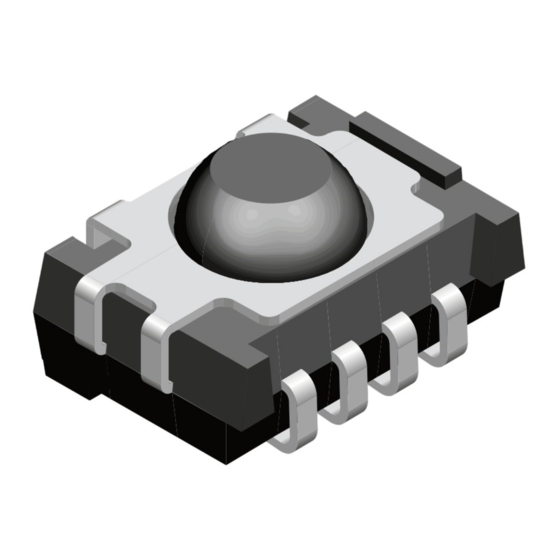
MECHANICAL DATA
Pinning
1 = GND, 2 = N.C., 3 = V
, 4 = OUT
S
ORDERING CODE
Taping:
TSOP6...TT - top view taped
TSOP6...TR - side view taped
PARTS TABLE
AGC
30 kHz
33 kHz
36 kHz
Carrier
frequency
38 kHz
40 kHz
56 kHz
Package
Pinning
Dimensions (mm)
Mounting
Application
Best choice for
Rev. 1.6, 26-Sep-2018
THIS DOCUMENT IS SUBJECT TO CHANGE WITHOUT NOTICE. THE PRODUCTS DESCRIBED HEREIN AND THIS DOCUMENT
ARE SUBJECT TO SPECIFIC DISCLAIMERS, SET FORTH AT
4
3
2
1
16797
click logo to get started
LEGACY, FOR SHORT BURST
REMOTE CONTROLS (AGC1)
TSOP6130
TSOP6133
TSOP6136
TSOP6138
TSOP6140
TSOP6156
(1)
(2)
MCIR
TSOP61.., TSOP63.., TSOP65..
FEATURES
• Improved immunity against HF and RF noise
• Low supply current
• Photo detector and preamplifier in one package
• Internal filter for PCM frequency
• Improved shielding against EMI
• Supply voltage: 2.5 V to 5.5 V
• Improved immunity against ambient light
• Insensitive to supply voltage ripple and noise
• Taping available for top view and side view
assembly
• Material categorization: for definitions of compliance
please see
www.vishay.com/doc?99912
DESCRIPTION
The TSOP61.., TSOP63.. series are miniaturized SMD
IR receivers for infrared remote control systems. A PIN
diode and a preamplifier are assembled on a lead frame, the
epoxy package contains an IR filter. The demodulated
output signal can be directly connected to a microprocessor
for decoding.
The TSOP63.. series devices are optimized to suppress
almost all spurious pulses from Wi-Fi and CFL sources.
They may suppress some data signals if continuously
transmitted.
The TSOP61.. series devices are provided primarily for
compatibility with old AGC1 designs. New designs should
prefer the TSOP63.. series containing the newer AGC3. The
TSOP65.. series are useful to suppress even extreme levels
of optical noise, but may also suppress some data signals.
Please check compatibility with your codes.
These components have not been qualified according to
automotive specifications.
NOISY ENVIRONMENTS
AND SHORT BURSTS (AGC3)
TSOP6330
TSOP6333
(1)
TSOP6336
(2)(3)(4)(5)
TSOP6338
TSOP6340
TSOP6356
Panhead
1 = GND, 2 = N.C., 3 = V
, 4 = OUT
S
7.5 W x 5.3 H x 4.0 D
SMD
Remote control
(3)
(4)
Mitsubishi
RECS-80 Code
1
www.vishay.com/doc?91000
Vishay Semiconductors
VERY NOISY ENVIRONMENTS
AND SHORT BURSTS (AGC5)
TSOP6530
TSOP6533
TSOP6536
(2)(3)(4)
TSOP6538
TSOP6540
TSOP6556
(5)
r-map
XMP-1, XMP-2
Document Number: 82457
(1)
Advertisement
Table of Contents

Related Manuals for Vishay TSOP63 Series


Summary of Contents for Vishay TSOP63 Series
- Page 1 TSOP61.., TSOP63.., TSOP65.. www.vishay.com Vishay Semiconductors IR Receiver Modules for Remote Control Systems FEATURES • Improved immunity against HF and RF noise • Low supply current • Photo detector and preamplifier in one package • Internal filter for PCM frequency •...
-
Page 2: Block Diagram
TSOP61.., TSOP63.., TSOP65.. www.vishay.com Vishay Semiconductors BLOCK DIAGRAM APPLICATION CIRCUIT 17170-11 Tran mitter 33 kΩ IR receiver with T ALxxxx Band Demo- μC Input pass dulator Control circuit and C recommended to reduce upply ripple for V < 2.8 V... -
Page 3: Typical Characteristics
TSOP61.., TSOP63.., TSOP65.. www.vishay.com Vishay Semiconductors TYPICAL CHARACTERISTICS (T = 25 °C, unless otherwise specified) Optical Test Signal (IR diode TSAL6200, I = 0.4 A, N = 6 pulses, f = f , t = 10 ms) ≥ 6/f 0 is recommended for optimal function... - Page 4 TSOP61.., TSOP63.., TSOP65.. www.vishay.com Vishay Semiconductors Axis Title 10000 f = f f = 30 kHz 1000 f = 20 kHz f = 10 kHz f = 100 Hz 1000 1050 1150 ΔV s - AC Voltage on DC Supply Voltage (mV) λ...
- Page 5 TSOP61.., TSOP63.., TSOP65.. www.vishay.com Vishay Semiconductors SUITABLE DATA FORMAT Axis Title This series is designed to suppress spurious output pulses 10000 due to noise or disturbance signals. The devices can distinguish data signals from noise due to differences in frequency, burst length, and envelope duty cycle. The data signal should be close to the device’s band-pass center...
- Page 6 TSOP61.., TSOP63.., TSOP65.. www.vishay.com Vishay Semiconductors PACKAGE DIMENSIONS in millimeters Pick and place area. TT taping (1.4) 0.5 ± 0.15 1.27 3 x 1.27 = 3.81 5.51 Not indicated tolerances ± 0.3 Pick and place area. TR taping technical drawings...
- Page 7 TSOP61.., TSOP63.., TSOP65.. www.vishay.com Vishay Semiconductors VISHAY LEAD (Pb)-FREE REFLOW SOLDER PROFILE Axis Title 10000 max. 260 °C 255 °C 245 °C 240 °C 217 °C 1000 max. 20 s max. 120 s max. 100 s Max. ramp up 3 °C/s Max.
- Page 8 TSOP61.., TSOP63.., TSOP65.. www.vishay.com Vishay Semiconductors TAPING VERSION TSOP..TR DIMENSIONS in millimeters 16585 Rev. 1.6, 26-Sep-2018 Document Number: 82457 THIS DOCUMENT IS SUBJECT TO CHANGE WITHOUT NOTICE. THE PRODUCTS DESCRIBED HEREIN AND THIS DOCUMENT ARE SUBJECT TO SPECIFIC DISCLAIMERS, SET FORTH AT...
- Page 9 165° to 180° peel angle with standard bar code labels before transported as finished goods to warehouses. The labels are on each packing unit and contain Vishay Semiconductor GmbH specific data. Rev. 1.6, 26-Sep-2018 Document Number: 82457 THIS DOCUMENT IS SUBJECT TO CHANGE WITHOUT NOTICE. THE PRODUCTS DESCRIBED HEREIN AND THIS DOCUMENT ARE SUBJECT TO SPECIFIC DISCLAIMERS, SET FORTH AT www.vishay.com/doc?91000...
- Page 10 TSOP61.., TSOP63.., TSOP65.. www.vishay.com Vishay Semiconductors VISHAY SEMICONDUCTOR GmbH STANDARD BAR CODE PRODUCT LABEL (finished goods) PLAIN WRITING ABBREVIATION LENGTH Item-description Item-number Selection-code LOT-/serial-number BATCH Data-code 3 (YWW) Plant-code Quantity Accepted by Packed by Mixed code indicator MIXED CODE Origin...
-
Page 11: Esd Precaution
Proper storage and handling procedures should be followed to prevent ESD damage to the devices especially when they The Vishay Semiconductors standard bar code labels are are removed from the antistatic shielding bag. Electrostatic printed at final packing areas. The labels are on each sensitive devices warning labels are on the packaging. - Page 12 Except as expressly indicated in writing, Vishay products are not designed for use in medical, life-saving, or life-sustaining applications or for any other application in which the failure of the Vishay product could result in personal injury or death. Customers using or selling Vishay products not expressly indicated for use in such applications do so at their own risk.
Need help?
Do you have a question about the TSOP63 Series and is the answer not in the manual?
Questions and answers