Advertisement
Quick Links
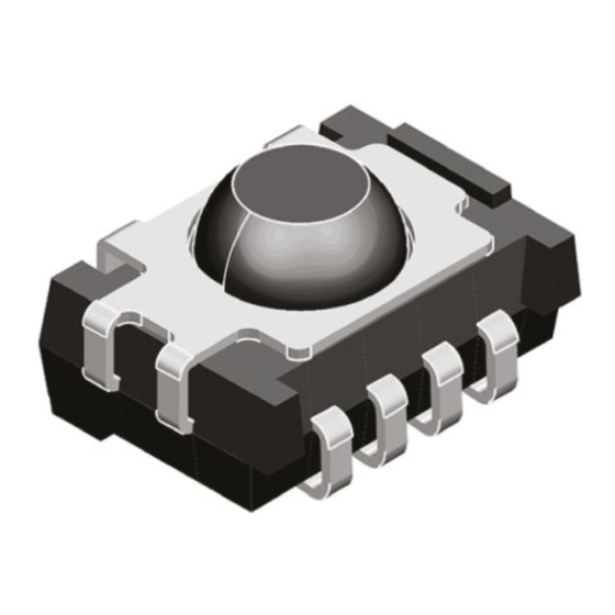
IR Receiver Modules for Remote Control Systems
MECHANICAL DATA
Pinning:
1 = GND, 2 = N.C., 3 = V
, 4 = OUT
S
PARTS TABLE
CARRIER FREQUENCY
30 kHz
33 kHz
36 kHz
38 kHz
40 kHz
56 kHz
BLOCK DIAGRAM
Input
AGC
PIN
Control circuit
16839
Document Number: 81780
Rev. 1.5, 09-Jul-10
4
3
2
1
16797
SHORT BURSTS AND HIGH
DATA RATES (AGC1)
TSOP35130
TSOP35133
TSOP35136
TSOP35138
TSOP35140
TSOP35156
3
V
S
30 kΩ
4
OUT
-
Band
Demo
dulator
pass
1; 2
GND
TSOP351.., TSOP353.., TSOP355..
FEATURES
• Very low supply current
• Photo detector and preamplifier in one
package
• Internal filter for PCM frequency
• Continuous data transmission possible
• Supply voltage: 2.5 V to 5.5 V
• Insensitive to supply voltage ripple and noise
• Compliant to RoHS directive 2002/95/EC and in
accordance to WEEE 2002/96/EC
• Taping available for topview and sideview assembly
DESCRIPTION
The TSOP351.., TSOP353.. and TSOP355.. series are
miniaturized SMD IR receiver modules for infrared remote
control systems. PIN diode and preamplifier are assembled
on a lead frame, the epoxy package is designed as IR filter.
The demodulated output signal can directly be decoded by
a microprocessor. The TSOP351.. is compatible with all
common IR remote control data formats. The TSOP353.. is
optimized to better suppress spurious pulses from energy
saving lamps. The TSOP355.. has an excellent noise
suppression. It is immune to dimmed LCD backlighting and
any fluorescent lamps. AGC3 and AGC5 may also suppress
some data signals in case of continuous transmission.
This component has not been qualified according to
automotive specifications.
NOISY ENVIRONMENTS AND
SHORT BURSTS (AGC3)
TSOP35330
TSOP35333
TSOP35336
TSOP35338
TSOP35340
TSOP35356
APPLICATION CIRCUIT
17170_5
Transmitter
IR receiver
with
TSALxxxx
R
and C
are recommended for protection against EOS.
1
1
Components should be in the range of 33 Ω < R
C
> 0.1 µF.
1
Vishay Semiconductors
VERY NOISY ENVIRONMENTS
AND SHORT BURSTS (AGC5)
TSOP35530
TSOP35533
TSOP35536
TSOP35538
TSOP35540
TSOP35556
R
1
V
S
C
1
µC
OUT
V
O
GND
< 1 kΩ,
1
www.vishay.com
+ V
S
GND
1
Advertisement

Related Manuals for Vishay TSOP351 Series


Summary of Contents for Vishay TSOP351 Series
- Page 1 TSOP351.., TSOP353.., TSOP355.. Vishay Semiconductors IR Receiver Modules for Remote Control Systems FEATURES • Very low supply current • Photo detector and preamplifier in one package • Internal filter for PCM frequency • Continuous data transmission possible • Supply voltage: 2.5 V to 5.5 V •...
-
Page 2: Absolute Maximum Ratings
TSOP351.., TSOP353.., TSOP355.. IR Receiver Modules for Remote Vishay Semiconductors Control Systems ABSOLUTE MAXIMUM RATINGS PARAMETER TEST CONDITION SYMBOL VALUE UNIT Supply voltage (pin 3) - 0.3 to + 6 Supply current (pin 3) Output voltage (pin 4) - 0.3 to (V + 0.3) - Page 3 TSOP351.., TSOP353.., TSOP355.. IR Receiver Modules for Remote Vishay Semiconductors Control Systems Optical Test Signal Correlation with Ambient Light Sources: 10 W/m = 1.4 kLx (Std. illum. A, T = 2855 K) 10 W/m = 8.2 kLx (Daylight, T = 5900 K) 600 µs...
- Page 4 TSOP351.., TSOP353.., TSOP355.. IR Receiver Modules for Remote Vishay Semiconductors Control Systems 0° 10° 20° 30° 40° TSOP351.. 50° f = 38 kHz, E = 2 mW/m² 60° 70° TSOP353.. 80° TSOP355.. 22180-3 - Relative Transmission Distance Burst Length (number of cycles/burst) 16801 Fig.
- Page 5 TSOP351.., TSOP353.., TSOP355.. IR Receiver Modules for Remote Vishay Semiconductors Control Systems SUITABLE DATA FORMAT The TSOP351.., TSOP353.. and TSOP355.. series is designed to suppress spurious output pulses due to noise or disturbance signals. Data and disturbance signals can be distinguished by the devices according to carrier frequency, burst length and envelope duty cycle.
- Page 6 TSOP351.., TSOP353.., TSOP355.. IR Receiver Modules for Remote Vishay Semiconductors Control Systems PACKAGE DIMENSIONS in millimeters Pick and place area. TT taping (1.4) 0.5 ± 0.15 1.27 3 x 1.27 = 3.81 5.51 Not indicated tolerances ± 0.3 Pick and place area. TR taping...
- Page 7 TSOP351.., TSOP353.., TSOP355.. IR Receiver Modules for Remote Vishay Semiconductors Control Systems VISHAY LEAD (Pb)-FREE REFLOW SOLDER PROFILE max. 260 °C 255 °C 245 °C 240 °C 217 °C max. 20 s max. 100 s max. 120 s max. Ramp Up 3 °C/s max.
- Page 8 TSOP351.., TSOP353.., TSOP355.. IR Receiver Modules for Remote Vishay Semiconductors Control Systems TAPING VERSION TSOP..TR Dimensions in millimeters 16585 www.vishay.com Document Number: 81780 Rev. 1.5, 09-Jul-10...
- Page 9 The standard packing units are labeled with standard bar code labels before transported as finished goods to warehouses. The labels are on each packing unit and contain Vishay Semiconductor GmbH specific data. Document Number: 81780 www.vishay.com Rev. 1.5, 09-Jul-10...
- Page 10 TSOP351.., TSOP353.., TSOP355.. IR Receiver Modules for Remote Vishay Semiconductors Control Systems VISHAY SEMICONDUCTOR GmbH STANDARD BAR CODE PRODUCT LABEL (finished goods) PLAIN WRITTING ABBREVIATION LENGTH Item-description Item-number Selection-code LOT-/serial-number BATCH Data-code 3 (YWW) Plant-code Quantity Accepted by Packed by...
-
Page 11: Esd Precaution
VISHAY SEMICONDUCTORS STANDARD BAR CODE LABELS The Vishay Semiconductors standard bar code labels are printed at final packing areas. The labels are on each packing unit and contain Vishay Semiconductors specific data. - Page 12 Vishay disclaims any and all liability arising out of the use or application of any product described herein or of any information provided herein to the maximum extent permitted by law. The product specifications do not expand or otherwise modify Vishay’s terms and conditions of purchase, including but not limited to the warranty expressed...
Need help?
Do you have a question about the TSOP351 Series and is the answer not in the manual?
Questions and answers