Xinje XL Series User Manual
Plc extension module
Hide thumbs
Also See for XL Series:
- User manual (195 pages) ,
- Manual (2 pages) ,
- User manual (390 pages)
Table of Contents
Advertisement
Quick Links
Advertisement
Table of Contents

Related Manuals for Xinje XL Series


Summary of Contents for Xinje XL Series
- Page 1 XL series PLC extension module User manual...
- Page 2 WUXI XINJE ELECTRIC CO., LTD. Copyright reserved Without exact paper file allowance, copy, translate or using the manual is not allowed. Disobey this, people should take the responsibility of loss.
-
Page 3: Table Of Contents
Catalog 1. MODULE INFORMATION SUMMARY .................. 1 1-1. M ................. 1 ODULE MODEL AND CONFIGURATION 1-2. D ........................2 IMENSION 1-3. P ....................4 ART NAME AND FUNCTION 1-4. G ....................5 ENERAL SPECIFICATION 1-5. M ....................... 6 ODULE INSTALLATION 1-6. - Page 4 5-7. D ........................66 IMENSION 5-8. A ........................66 PPLICATION 6. ANALOG OUTPUT MODULE XL-E4DA ................67 6-1. M ................68 ODULE FEATURES AND SPECIFICATIONS 6-2. T ....................68 ERMINAL DESCRIPTION 6-3. I/O ........................70 ADDRESS 6-4. W ....................73 ORKING MODE SETTINGS 6-5.
-
Page 5: Module Information Summary
4 channels PT100 temperature measurement, with PID function XL-E4TC-P 4 channels thermocouple temperature measurement, with PID function Module configuration XL series expansion module can be installed on the right side of the main unit and expansion module of XL series PLC. -
Page 6: Dimension
Note: When the number of right extension modules connected by XL series PLC is more than 5, it is necessary to connect a terminal resistance module XL-ETR to the right of the last module (requiring the hardware version of XL series right extension module to be H3.1 or more). - Page 7 The shape and size of XL series 32-point I/O modules are shown in the following figure: (unit: mm)
-
Page 8: Part Name And Function
1-3. Part name and function Name Function Fixed buckle fix the PLC unit and extension module Module model The extension module model Extension port To connect other modules I/O terminal Connect analog input and output, external devices, removable Power LED The LED lights up when the module has power supply. -
Page 9: General Specification
1-4. General specification Operating Environment No corrosive gas Ambient Temperature 0℃~60℃ Store Temperature -20~70℃ Ambient Humidity 5~95% RH Store Humidity 5~95% RH Can be fixed with M3 screw or directly installed on Installation DIN46277 rail (width: 35mm) Operating Environment No corrosive gas... -
Page 10: Module Installation
1-5. Module installation Installation steps 1. Check installation environment Check the suitability of special function module installation site 2. Installation preparation Prepare for installation of special modules 3. Module installation Install the module on the right side of PLC 4. Debugging Check whether the module is installed correctly... - Page 11 A place where a strong magnetic field or electric field is produced Installation requirement XL series analog input and output, temperature control module can be installed on the right side of the main unit and expansion module of XL series PLC. The installation can use DIN46277 guideway (35 mm wide).
-
Page 12: Configuration Of The Module
Wiring requirement Apart from the XL series 32-point extension module, which needs to use an external terminal for wiring, other modules can directly insert the cable into the corresponding wiring hole. Cautions: 1. Please confirm the specifications and select the appropriate modules. -
Page 13: Terminal Resistance Module Xl-Etr
Note: please use software version 3.5.1 and higher to configure the modules. 1-7. Terminal resistance module XL-ETR When the number of right extension modules of XL series PLC is more than 5, the terminal resistance module XL-ETR must be used together. - Page 14 XL-E4AD2DA XL-E4AD2DA XL-E4AD2DA Installation location When using, please install XL-ETR on the right side of the last extension module and connect the interface slot of the module as shown in the following figure:...
-
Page 15: I/O Extension Module Xl-Enxmy
2-1. Module features and specifications XL series PLC can expand XL-EnXmY input and output module externally. Each XL3 series PLC can expand 10 modules, XL5/XL5E can expand 16 modules, XL1 does not support expansion module. The module is rich in types and compact in shape, which makes it possible for more input and output points and meets the actual production needs. -
Page 16: Terminal Descriptions
XL-E32X 32 channels digital input XL-E32YT 32 channels transistor output Module specification Item Specification Power supply DC24V±10% Environment Non-corrosive gas Temperature 0℃~60℃ Humidity 5~95% Installation Direct mounting on DIN46277 (35 mm wide) rail 2-2. Terminal descriptions XL-E8X8YR, XL-E8X8YT terminal arrangement: XL-E16X terminal arrangement: XL-E16YR, XL-E16YT terminal arrangement: XL-E16X16YT terminal arrangement:... -
Page 17: I/Odefinition Number
(2) Flexible conductors with bare tubular ends are 0.25-1.5 square meter. (3) Flexible conductor with tubular pre-insulated end is 0.25-0.5 square meter. 2-3. I/O definition number The addresses of the input and output terminals of the XL Series I/O Extension Module are as follows: ⚫... - Page 18 X11010 X11110 X11210 X11310 X11410 X11510 X11610 X11710 … … … … … … … … … X11017 X11117 X11217 X11317 X11417 X11517 X11617 X11717 X11020 X11120 X11220 X11320 X11420 X11520 X11620 X11720 … … … … … … … …...
-
Page 19: External Connection
2-wire (NO/NC) proximity switch wiring example 3-wire (NPN) proximity switch wiring example XL-E32X, XL-E16X16YT and XL-E32YT modules need external terminals. Xinje provides adapter terminals and connection cables for users to choose from. A list of module models and adapter terminals and connecting cables:... - Page 20 ⚫ Connection cable External terminals need to cooperate with the use of connecting cables, Xinje provides JC-TE32-NNN05, JC-TE32-NN10, JC-TE32-NN15 three different length of cables for users to choose and purchase. When connecting, please note that the end closing to the transparent...
- Page 21 Output wiring method: Relay type Transistor type...
-
Page 22: Module Parameters
2-5. Module parameters Positive and negative logic can be adjusted and filtering time can be adjusted. There are two configuration modes: A. Set through the software B. Set through SFD register Module Module SFD address SFD address number number SFD350~SFD359 SFD430~SFD439 SFD360~SFD369 SFD440~SFD449... - Page 23 Bit3 Bit2 X1 logic X5 logic Y1 logic Y5 logic Bit1 Bit0 X0 logic X4 logic Y0 logic Y4 logic Filtering time (unit: ms): Note: 0 is positive logic, 1 is negative Notes 1~5, 10(default), 15, 20, 25, 30, logic 35, 40, 45, 50 ⚫...
- Page 24 Byte10 logic logic logic logic Byte11 logic logic logic logic Byte 12~19 ⚫ XL-E16Y/XL-E32Y Bit0 Bit1 Bit2 Bit3 Bit4 Bit5 Bit6 Bit7 Explanation Byte0 Y1logic logic logic logic Byte1 Note: 0 is positive logic logic logic logic logic, 1 is negative Byte2 logic logic...
-
Page 25: Dimension
In negative logic, X terminal is ON, X terminal signal is OFF, X terminal is OFF, X-terminal signal is ON. Default is positive logic, usually without modification. 2-6. Dimension The shape and size of XL series 8-16 I/O modules are shown in the following figure: (Unit: mm) 15.0 70.0 25.0... -
Page 26: Application
2-7. Application In this chapter, the application of this module will be exemplified. XL3-16R is slave station with an extended XL-E8X8YR to communicate with XINJE HMI. Communication between Extended Module XL-E8X8YR and Xinje TG765 HMI. THINGET MODE: TG760T-MT S/ N: N20121028028 Xinje Electronic Co.,Ltd... - Page 27 The module XL-E8X8YR is attached to XL3-16R, and the RS485 communication terminal AB of XL3-16R is connected to the AB terminal of the PLC port of TG765 respectively. Communication parameter settings: the baud rate is 19200 bps, 8 data bits, 1 stop bit, even parity, PLC Modbus station number is 1, then cut the power supply and power on again.
- Page 28 Edit the PSB501 status, place a lamp, the lamp object type is PSB, the coil number is 501. When the function button is pressed, copy the status of PSB501 to extension module Y10000.
- Page 29 Edit the status of extension module Y10000, the lamp object type is 0x, the modbus address is 24832. Download the program into the HMI. Then make them to communicate.
-
Page 30: Analog I/O Module Xl-E4Ad2Da
⚫ 14-bit high-precision analog input. ⚫ 2-channel 12-bit analog output. ⚫ As an extension module of XL series, XL3 can connect up to 10 modules, XL5/XL5E can expand 16 modules, XL1 does not support extension modules. Module specification Items... -
Page 31: Terminal Description
(0~4095 or -2048~2047) 14 bits binary data Digital output range (0~16383 or -8192~8191) Resolution 1/16383(14Bit) 1/4095(12Bit) Integrated precision Conversion speed 2ms per channel 2ms per channel Module power supply DC24V±10%,150mA Fixed with M3 screws or directly installed on orbit of DIN46277 (Width: Installation 35mm) 3-2. -
Page 32: I/Oaddress
(3) Flexible wires with tubular pre-insulated end is 0.25-0.5 square. 3-3. I/O address XL series analog module does not occupy I/O unit, the converted value is directly sent to the PLC register, the corresponding channel definition number of the PLC register is as follows:... - Page 33 Module 2 register address: Channel enable switch Channel AD signal (please turn on the swich to use this channel) ID10100 Y10100 ID10101 Y10101 ID10102 Y10102 ID10103 Y10103 Channel DA signal QD10100 Y10104 QD10101 Y10105 Module 3 register address: Channel enable switch Channel AD signal (please turn on the swich to use this...
- Page 34 ID10403 Y10403 Channel DA signal QD10400 Y10404 QD10401 Y10405 Module 6 register address: Channel enable switch Channel AD signal (please turn on the swich to use this channel) ID10500 Y10500 ID10501 Y10501 ID10502 Y10502 ID10503 Y10503 Channel DA signal QD10500 Y10504 QD10501 Y10505...
- Page 35 Module 9 register address: Channel enable switch Channel AD signal (please turn on the swich to use this channel) ID10800 Y11000 ID10801 Y11001 ID10802 Y11002 ID10803 Y11003 Channel DA signal QD10800 Y11004 QD10801 Y11005 Module 10 register address: Channel enable switch Channel AD signal (please turn on the swich to use this...
- Page 36 ID11103 Y11303 Channel DA signal QD11100 Y11304 QD11101 Y11305 Module 13 register address: Channel enable switch Channel AD signal (please turn on the swich to use this channel) ID11200 Y11400 ID11201 Y11401 ID11202 Y11402 ID11203 Y11403 Channel DA signal QD11200 Y11404 QD11201 Y11405...
-
Page 37: Working Mode Settings
Module 16 register address: Channel enable switch Channel AD signal (please turn on the swich to use this channel) ID11500 Y11700 ID11501 Y11701 ID11502 Y11702 ID11503 Y11703 Channel DA signal QD11500 Y11704 QD11501 Y11705 Note: (1) Banning unused channels can improve the scanning speed of input/output. (2) When the input enable switch is turned off during operation, the corresponding input channel will not collect data. - Page 38 Choose the module type, and set each channel’s parameters in the above window. Then click write to PLC, cut the power supply and power on again to make the settings effective. Note: The first-order low-pass filtering method weighs this time sampling value and the output value of the last filtering to get the effective filtering value;...
- Page 39 SFD bit definition Take the first module as an example to illustrate how to set it up. Bit7 Bit6 Bit5 Bit4 Bit3 Bit2 Bit1 Bit0 NOTE Byte0 AD channel 1, channel 2 filtering parameter filtering Byte1 AD channel 3, channel 4 filtering parameter parameter Bit7 Bit6...
-
Page 40: External Wiring
Method 2: Set the SFD as follows: SFD350=64FEH SFD351=2301H SFD352=0002H 3-5. External wiring For external connection, to avoid interference, use shielding wire and connect the ground to the single point of shielding layer. Voltage input Voltage output... - Page 41 Current input XL-E4AD2DA current input wiring: Current output Note: current output no need DC24V power supply.
-
Page 42: Analog Digital Conversion Diagram
3-6. Analog digital conversion diagram The relationship between input analog quantities and converted digital quantities is shown in the following table: 0~5V analog input 0~10V analog input -5~5V analog input -10~10V analog input 0~20mA analog input 4~20mA analog input -20~20mA analog input 8191 digital -20mA... - Page 43 The relationship between the output digital quantity and its corresponding analog data is shown in the following table: 0~5V analog output 0~10V analog output -5~5V analog output -10~10V analog output 0~20mA analog output 4~20mA analog output Note: (1) When the AD voltage input is suspended, the corresponding ID register is 16383; when the AD current input is suspended, the corresponding ID register is 0.
-
Page 44: Dimension
3-7. Dimension (Unit: mm) XL-E4AD2DA 3-8. Application Example: The output signal of one-channel pressure sensor needs to be collected (pressure sensor performance parameters: detection pressure range 0Mp~10Mp, output analog signal 4~20mA), and output one-channel 0V~10V voltage signal to frequency converter. Analysis: As the pressure detection range of pressure sensor is 0Mp~10Mp, the analog output is 4~20mA, and the digital conversion range of expansion module is 0~16383, we can skip the analog amount of 4~20mA in the intermediate conversion process, which directly means that... - Page 45 Note: Please use floating-point number to calculate, otherwise it will affect the accuracy of calculation and even can not be calculated! Explanation: SM0 is a constant ON coil and has been in ON state during the operation of PLC. The PLC starts to run. The analog acquisition first calculates the pressure value corresponding to each digit 1 collected by the expansion module, and then converts the digital quantity (integer) collected in the ID10000 register into floating-point numbers.
-
Page 46: Analog Input Module Xl-E8Ad-A
8-channel analog input: current input. ⚫ 14-bit high-precision analog input. ⚫ As a special function module of XL series, XL3 can connect up to 10 modules, XL5/XL5E can expand 16 modules, XL1 does not support expansion modules. Module specification Analog input... -
Page 47: Terminal Descriptions
Installation Fixed with M3 screws or directly installed on rail of DIN46277 (Width: 35mm) 4-2. Terminal descriptions Terminal arrangment Terminal signal Name Function The indicator lights up when the module has a power supply. When the module port communicates normally, the indicator lights on. -
Page 48: I/Oaddress
(3) Flexible wires with tubular pre-insulated end is 0.25-0.5 square. 4-3. I/O address XL series analog module does not occupy I/O unit, the converted value is directly sent to the PLC register, the corresponding channel definition number of the PLC register is as follows:... - Page 49 ID10105 Y10105 ID10106 Y10106 ID10107 Y10107 Module 3 register address: Channel enable switch Channel AD signal (please turn on the swich to use this channel) ID10200 Y10200 ID10201 Y10201 ID10202 Y10202 ID10203 Y10203 ID10204 Y10204 ID10205 Y10205 ID10206 Y10206 ID10207 Y10207 Module 4 register address: Channel enable switch...
- Page 50 Module 6 register address: Channel enable switch Channel AD signal (please turn on the swich to use this channel) ID10500 Y10500 ID10501 Y10501 ID10502 Y10502 ID10503 Y10503 ID10504 Y10504 ID10505 Y10505 ID10506 Y10506 ID10507 Y10507 Module 7 register address: Channel enable switch Channel AD signal (please turn on the swich to use this...
- Page 51 Module 9 register address: Channel enable switch Channel AD signal (please turn on the swich to use this channel) ID10800 Y11000 ID10801 Y11001 ID10802 Y11002 ID10803 Y11003 ID10804 Y11004 ID10805 Y11005 ID10806 Y11006 ID10807 Y11007 Module 10 register address: Channel enable switch Channel AD signal (please turn on the swich to use this...
- Page 52 Module 12 register address: Channel enable switch Channel AD signal (please turn on the swich to use this channel) ID11100 Y11300 ID11101 Y11301 ID11102 Y11302 ID11103 Y11303 ID11104 Y11304 ID11105 Y11305 ID11106 Y11306 ID11107 Y11307 Module 13 register address: Channel enable switch Channel AD signal (please turn on the swich to use this...
-
Page 53: Working Mode Settings
Module 15 register address: Channel enable switch Channel AD signal (please turn on the swich to use this channel) ID11400 Y11600 ID11401 Y11601 ID11402 Y11602 ID11403 Y11603 ID11404 Y11604 ID11405 Y11605 ID11406 Y11606 ID11407 Y11607 Module 16 register address: Channel enable switch Channel AD signal (please turn on the swich to use this... - Page 54 Choose the module type, and set each channel’s parameters in the above window. Then click write to PLC, cut the power supply and power on again to make the settings effective. Note: The first-order low-pass filtering method weighs this time sampling value and the output value of the last filtering to get the effective filtering value;...
- Page 55 SFD420~SFD429 SFD500~SFD509 Note: As shown above, each register sets four-channel modes. Each register has 16 bits. From low to high, each four bit will set four-channel modes in turn. SFD bit definition NOTE Bit7 Bit6 Bit5 Bit4 Bit3 Bit2 Bit1 Bit0 Byte0 AD channel 2, channel 1 filtering parameter...
-
Page 56: External Wiring
Method 1: You can configure it directly in the PLC software, as shown above. Method 2: Set the SFD as follows: SFD350=FEFEH SFD351=6464H SFD352=9988H SFD353=AA88H 4-5. External wiring For external connection, to avoid interference, use shielding wire and connect the ground to the single point of shielding layer. -
Page 57: Analog Digital Conversion Diagram
4-6. Analog digital conversion diagram The relationship between input analog quantities and converted digital quantities is shown in the following table: 0~20mA analog input 4~20mA analog input -20~20mA analog input 4-7. Dimension (Unit: mm) 15.0 70.0 25.0 XL-E8AD-A... -
Page 58: Application
4-8. Application Examples of real-time reading 8 channels of data (take Module 1 as an example) ID10000 ID10001 ID10002 ID10003 ID10004 ID10005 ID10006 ID10007 MSET Y10000 Y10007 Explain: SM0 is a constant ON coil and has been in ON state during the operation of PLC. The PLC starts to run, and continuously writes the data of channel 0 of the module 1 into the data register D0. -
Page 59: Module Features And Specifications
8-channel analog input: voltage input. ⚫ 14-bit high-precision analog input. ⚫ As a special function module of XL series, XL3 can connect up to 10 modules, XL5/XL5E can expand 16 modules, XL1 does not support expansion modules. Module specification Analog input... - Page 60 Terminal signal Name Function The indicator lights up when the module has a power supply. When the module port communicates normally, the indicator lights on. When there is an error in the module, the indicator is always on or flickering (red). Indicator When the ERR LED is always on, it indicates that the module light...
-
Page 61: I/Oaddress
(3) Flexible wires with tubular pre-insulated end is 0.25-0.5 square. 5-3. I/O address XL series analog module does not occupy I/O unit, the converted value is directly sent to the PLC register, the corresponding channel definition number of the PLC register is as follows:... - Page 62 ID10201 Y10201 ID10202 Y10202 ID10203 Y10203 ID10204 Y10204 ID10205 Y10205 ID10206 Y10206 ID10207 Y10207 Module 4 register address: Channel enable switch Channel AD signal (please turn on the swich to use this channel) ID10300 Y10300 ID10301 Y10301 ID10302 Y10302 ID10303 Y10303 ID10304 Y10304...
- Page 63 ID10504 Y10504 ID10505 Y10505 ID10506 Y10506 ID10507 Y10507 Module 7 register address: Channel enable switch Channel AD signal (please turn on the swich to use this channel) ID10600 Y10600 ID10601 Y10601 ID10602 Y10602 ID10603 Y10603 ID10604 Y10604 ID10605 Y10605 ID10606 Y10606 ID10607 Y10607...
- Page 64 ID10804 Y11004 ID10805 Y11005 ID10806 Y11006 ID10807 Y11007 Module 10 register address: Channel enable switch Channel AD signal (please turn on the swich to use this channel) ID10900 Y11100 ID10901 Y11101 ID10902 Y11102 ID10903 Y11103 ID10904 Y11104 ID10905 Y11105 ID10906 Y11106 ID10907 Y11107...
- Page 65 ID11104 Y11304 ID11105 Y11305 ID11106 Y11306 ID11107 Y11307 Module 13 register address: Channel enable switch Channel AD signal (please turn on the swich to use this channel) ID11200 Y11400 ID11201 Y11401 ID11202 Y11402 ID11203 Y11403 ID11204 Y11404 ID11205 Y11405 ID11206 Y11406 ID11207 Y11407...
-
Page 66: Working Mode Settings
ID11404 Y11604 ID11405 Y11605 ID11406 Y11606 ID11407 Y11607 Module 16 register address: Channel enable switch Channel AD signal (please turn on the swich to use this channel) ID11500 Y11700 ID11501 Y11701 ID11502 Y11702 ID11503 Y11703 ID11504 Y11704 ID11505 Y11705 ID11506 Y11706 ID11507 Y11707... - Page 67 Choose the module type, and set each channel’s parameters in the above window. Then click write to PLC, cut the power supply and power on again to make the settings effective. Note: The first-order low-pass filtering method weighs this time sampling value and the output value of the last filtering to get the effective filtering value;...
- Page 68 NOTE Bit7 Bit6 Bit5 Bit4 Bit3 Bit2 Bit1 Bit0 Byte0 AD channel 2, channel 1 filtering parameter Byte1 AD channel 4, channel 3 filtering parameter AD filtering parameter Byte2 AD channel 6, channel 5 filtering parameter Byte3 AD channel 8, channel 7 filtering parameter Bit7 Bit6 Bit5...
-
Page 69: External Wiring
SFD350=FEFEH SFD351=6464H SFD352=1100H SFD353=1100H 5-5. External wiring For external connection, to avoid interference, use shielding wire and connect the ground to the single point of shielding layer. Voltage input 5-6. Analog digital conversion diagram The relationship between input analog quantities and converted digital quantities is shown in the following table: 0~5V analog input 0~10V analog input... -
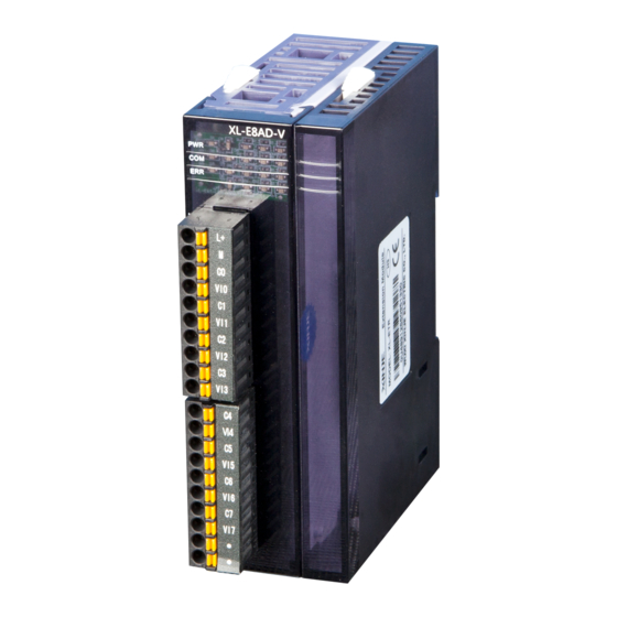
Page 70: Dimension
-5~5V analog input -10~10V analog input 5-7. Dimension (Unit: mm) 15.0 70.0 25.0 XL-E8AD-V 5-8. Application Examples of real-time reading 8 channels of data (take Module 1 as an example) -
Page 71: Analog Output Module Xl-E4Da
ID10000 ID10001 ID10002 ID10003 ID10004 ID10005 ID10006 ID10007 MSET Y10000 Y10007 Explain: SM0 is a constant ON coil and has been in ON state during the operation of PLC. The PLC starts to run, and continuously writes the data of channel 0 of the module 1 into the data register D0. -
Page 72: Module Features And Specifications
Four-channel analog output: Voltage and current mode can be selected. 模拟量输出端 ⚫ 12-bit high-precision analog output. ⚫ As an extension module of XL series, XL3 can connect up to 10 modules, XL5/XL5E can expand 16 modules, XL1 does not support extension 扩展口 modules. 25.0 15.0... - Page 73 Terminal signal Name Function The indicator lights up when the module has a power supply. When the module port communicates normally, the indicator lights on. When there is an error in the module, the indicator is always on or flickering (red). Indicator When the ERR LED is always on, it indicates that the module has light...
-
Page 74: I/Oaddress
(3) Flexible wires with tubular pre-insulated end is 0.25-0.5 square. 6-3. I/O address XL series analog module does not occupy I/O unit, the converted value is directly sent to the PLC register, the corresponding channel definition number of the PLC register is as follows:... - Page 75 QD10301 Y10301 QD10302 Y10302 QD10303 Y10303 Module 5 register address: Channel enable switch Channel DA signal (please turn on the swich to use this channel) QD10400 Y10400 QD10401 Y10401 QD10402 Y10402 QD10403 Y10403 Module 6 register address: Channel enable switch Channel DA signal (please turn on the swich to use this...
- Page 76 channel) QD10800 Y11000 QD10801 Y11001 QD10802 Y11002 QD10803 Y11003 Module 10 register address: Channel enable switch Channel DA signal (please turn on the swich to use this channel) QD10900 Y11100 QD10901 Y11101 QD10902 Y11102 QD10903 Y11103 Module 11 register address: Channel enable switch Channel DA signal...
-
Page 77: Working Mode Settings
QD11201 Y11401 QD11202 Y11402 QD11203 Y11403 Module 14 register address: Channel enable switch Channel DA signal (please turn on the swich to use this channel) QD11300 Y11500 QD11301 Y11501 QD11302 Y11502 QD11303 Y11503 Module 15 register address: Channel enable switch Channel DA signal (please turn on the swich to use this... - Page 78 (2) Setting up by Flash Register Set through the software Please use XDPpro v3.5.1 or higher version software to configure the module. Open the software, click module in the left menu, Choose the module type, and set each channel’s parameters in the above window. Then click write to PLC, cut the power supply and power on again to make the settings effective.
- Page 79 The output channels of the expansion module can be selected in two modes: voltage and current. Current is 0-20mA, 4-20mA. Voltage is 0-5V, 0-10V, -5-5V and -10-10V. It is set by special FLASH data register SFD in PLC. As follows: Module no.
-
Page 80: External Wiring
Method 1: You can configure it directly in the PLC software, the configuration method please refer to chapter 6-4. Method 2: Set the SFD as follows: SFD350=0022H 6-5. External wiring For external connection, to avoid interference, use shielding wire and connect the ground to the single point of shielding layer. -
Page 81: Nalog Digital Conversion Diagram
XL-E4DA current output wiring: Note: current output no needs to connect DC24V power supply. 6-6. Analog digital conversion diagram The relationship between the output digital quantity and its corresponding analog data is shown in the following table: 0~5V analog output 0~10V analog output -5~5V analog output -10~10V analog output... -
Page 82: Dimension
Note: When the input data exceeds K4095, the analog data of DA conversion remains unchanged at 5V, 10V or 20mA. 6-7. Dimension (Unit: mm) XL-E4DA 6-8. Application Example: real-time write 4 channels data(take module 1 as an example) -
Page 83: Pt100 Temperature Module Xl-E4Pt3-P
MOV D10 QD10000 MOV D11 QD10001 MOV D12 QD10002 MOV D13 QD10003 MSET Y10000 Y10003 Explain: SM0 is a constant ON coil and has been in ON state during the operation of PLC. Write the data register D10 to output channel 0. Write the data register D11 to output channel 1. -
Page 84: Terminals
XL-E4PT3-P Features ⚫ Platinum thermal resistance input, indexing number Pt100 ⚫ 4 channels input, 4 channels output ⚫ 4 groups PID parameters, auto-tune function ⚫ The constant current output of 1mA is not affected by the change of external environment. ⚫... - Page 85 Module signal Name Function The indicator lights up when the module has a power supply When the module communication port communicates normally, the indicator lights on When there is an error in the module, the indicator is always on or flickering (red) light When the ERR lamp is always on, there are serious application...
-
Page 86: I/Oaddress
(3) Flexible conductor with tubular pre-insulated end is 0.25-0.5 square. 7-3. I/O address XL series analog module will not occupy I/O unit, the conversion value will be sent to PLC register. Each channel related PLC register address are shown as below:... - Page 87 range ( Diff ) range of the PID is Target-Tdiff < T < Target + Tdiff, when T < Target-Tdiff, the Unit: 0.1℃ output is the largest, when T > Target + Tdiff, the output is 0. Temperature The actual temperature display = (sampling temperature value + temperature deviation value δ...
-
Page 88: Working Mode
FROM K10000 K0 K2 D0 Function: read the module data to the PLC regsiter, the operate unit is word. S1: target module number, range: 10000~10015. Operand: K, TD, CD, D, HD, FD S2: first address of module. Operand: K, TD, CD, D, HD, FD S3: read register numbers. - Page 89 Please use XDPPro software V3.5.1 and up to set the module. Open the software, click configure/expansion module setting, then select the module type in the following window: Choose the module model, set the filter parameter of each channel, click write to PLC. Then download user program and run, the settings will be effective.
-
Page 90: External Wiring
SFD bit definition Take module 1 as an example to explain the setting method: NOTE Bit7 Bit6 Bit5 Bit4 Bit3 Bit2 Bit1 Bit0 Byte0 AD channel 2, channel 1 filtering parameter AD filtering Byte1 AD channel 4, channel 3 filtering parameter parameter Byte2~Byte19 7-5. -
Page 91: Dimension
Power supply heater Solid state relay PT100 Input characteristic curve 5000 Digital output -100 Temperature -1000 input 7-6. Dimension (Unit: mm) -
Page 92: Application
XL-E4PT3-P 7-7. Application Example: take module 1 as an example, do PID control for channel 0. - Page 93 Y10000 // open PID enable bit MOV HD0 D0 // set target value MOV HD1 D1 // set operation range MOV HD2 D2 // set temperature control period SBLOCK Write in target value // write in the target value, operation range and TO K10000 K5 K1 D0 temperature control period TO K10000 K12 K1 D1...
- Page 94 write in target value, operation range, temperature control period turn on the auto-tune manual set the P, I, D parameter write in manual P, I, D parameter read the auto-tuning bit, PID parameters and PID output value Y10000 PID enable bit of channel 0 HD0 target value HD1 operation range HD2 temperature control period...
- Page 96 8. Thermocouple temperature module XL-E4TC-P This chapter mainly introduces XL-E4TC-P module specifications, terminal instructions, input definition number allocation, working mode settings, external connections, analog-to-digital conversion diagrams, appearance size diagrams and related programming examples. 8-1. Specifications XL-E4TC-P can process 4-channel of thermocouple signal and send the data to the PLC. XL-E4TC-P Features ⚫...
-
Page 97: Terminals
(3) Flexible conductor with tubular pre-insulated end is 0.25-0.5 square. 8-3. I/O address assignment XL series analog module will not occupy I/O unit, the conversion value will be sent to PLC register. Each channel related PLC register address are shown as below:... - Page 98 Channel Module 1 ID10000 ID10001 ID10002 ID10003 Unit: 0.1 ℃ Module 2 ID10100 ID10101 ID10102 ID10103 Display temperature ID10×00 ID10×01 ID10×02 ID10×03 Module 16 ID11500 ID11501 ID11502 ID11503 Module 1 X10000 X10001 X10002 X10003 Module 2 X10100 X10101 X10102 X10103 PID output ...
- Page 99 the module calculates the difference between the acquisition temperature and temperatur the actual temperature according to the value, and saves it. Calculate temperature deviation value δ = actual input temperature-sampling Unit: 0.1℃ temperature. (Note: Do not write this value at will, otherwise it will cause display temperature error) auto-tune The input of auto-tuning, the unit is % and input 100 is expressed as full scale...
-
Page 100: Working Mode
8-4. Working mode Set via software Please use XDPPro software V3.5.1 and up to set the module. Open the software, click configure/expansion module setting, then select the module type in the following window: Set the thermocoupler of each channel, click write to PLC and ok. Then download user program and run, the settings will be effective. -
Page 101: External Connection
thermocouple K:0000 K:0000 type of each S:0001 S:0001 channel, each E:0010 E:0010 channel occupies N:0011 N:0011 4 bits. J:0100 J:0100 T:0101 T:0101 R:0110 R:0110 B:0111 B:0111 TC3 channel TC2 channel K:0000 K:0000 S:0001 S:0001 E:0010 E:0010 Byte1 N:0011 N:0011 J:0100 J:0100 T:0101 T:0101... -
Page 102: Dimension
⚫ Output circuit Each point current is 0.15A to avoid over-heating. ⚫ Open circuit leak current Below 0.1mA. Power supply Heating unit Thermocouple input characteristic curve 8-6. Dimension The outline and dimension: (unit: mm) -
Page 103: Programming Example
15.0 70.0 25.0 XL-E4TC-P 8-7. Programming example Example: Do PID control for CH0 of module 1. - Page 104 Y10000 // open PID enable bit // set target value MOV HD0 D0 // set operation range MOV HD1 D1 // set control period MOV HD2 D2 // write in the target value, operation range, control period SBLOCK Target value TO K10000 K5 K1 D0 TO K10000 K12 K1 D1 // start the auto-tune function...
- Page 105 Que esse conteúdo tenha agregado valor e conhecimento pra você! Seu contato é importante para nós! • www.kalatec.com.br • Instagram - @kalateceautomação • Facebook - kalatecautomação NOSSAS FILIAIS Matriz Campinas – SP Filial São Paulo – SP Filial Joinville – SC Rua Salto, 99 Av.
Need help?
Do you have a question about the XL Series and is the answer not in the manual?
Questions and answers