Sign In
Upload
Manuals
Brands
Xinje Manuals
Controller
XL Series
Xinje XL Series Logic Controller Manuals
Manuals and User Guides for Xinje XL Series Logic Controller. We have
5
Xinje XL Series Logic Controller manuals available for free PDF download: User Manual, Manual
Xinje XL Series User Manual (390 pages)
Brand:
Xinje
| Category:
Controller
| Size: 8 MB
Table of Contents
Table of Contents
4
Programming Summary
10
PLC Features
10
Security of the Program
10
Rich Basic Functions
10
Programming Language
11
Stop PLC When Reboot
11
Programming Mode
12
Direct Input
12
Instruction Configuration
12
Soft Component Function
13
Summary of the Soft Components
13
Input Relay (X)
13
Output Relay (Y)
13
Auxiliary Relays (M, HM)
14
Status Relays (S, HS)
14
Timer (T, HT)
14
Counter (C, HC)
15
Data Register (D, HD)
15
Flashrom Register (FD)
15
Special Secret Register
16
Structure of Soft Components
16
Structure of Memory
16
Data Register
16
Timer T, Ht/Counter C, HC
17
Flashrom Register FD
17
Register Combined by Bits
17
Structure of Bit Soft Components
18
Relay
18
The Bit of Register
18
Soft Components List
19
Input/Output Relays (X, Y)
36
Auxiliary Relay (M, HM, SM)
38
Status Relay (S, HS)
39
Time Value
43
Counter ( C, HC )
44
Word Consist of Bits
52
Offset Application
53
Flash Register (FD, SFD, FS)
54
Constant
55
Programming Principle
56
BCD: Binary Code Decimal
56
Basic Program Instructions
60
Basic Instructions List
60
[Ld] , [Ldi] , [Out]
62
Mnemonic and Function
62
Statement
62
[And] , [Ani]
63
[Or] , [Ori]
64
[Ldp], [Ldf], [Andp], [Andf], [Orp], [Orf]
65
Relationship with ANB
65
[Ldd], [Lddi], [Andd], [Anddi], [Ord], [Ordi], [Outd]
66
[Orb]
67
[Anb]
68
[Mcs] , [Mcr]
69
[Alt]
70
[Pls], [Plf]
71
[Set], [Rst]
72
[CNT] [CNT_D] [DCNT] [DCNT_D] [RST] for the Counters
73
[TMR], [TMR-A] for Timers
75
[Group], [Groupe]
76
Programming Notes
77
Contactor Structure and Steps
77
Program’s Executing Sequence
77
Applied Instructions List
79
Reading Method of Applied Instructions
83
Program Flow Instructions
85
Condition Jump [CJ]
85
Call Subroutine [CALL] and Subroutine Return [SRET]
86
Flow [SET], [ST], [STL], [STLE]
88
[FOR] and [NEXT]
93
[FEND] and [END]
95
Data Compare Function
96
LD Compare [LD]
97
Serial Compare [AND]
98
Parallel Compare [OR]
99
Data Move Instructions
102
Data Compare [CMP]
102
Data Zone Compare [ZCP]
103
Mov [Mov]
104
Data Block Move [BMOV]
106
Data Block Move [PMOV]
107
Fill Move [FMOV]
108
Floating Move [EMOV]
110
Flashrom Write [FWRT]
111
Zone Set [MSET]
112
Zone Reset [ZRST]
113
Swap the High and Low Byte [SWAP]
114
Exchange [XCH]
115
Data Operation Instructions
117
Addition [ADD]
117
Subtraction [SUB]
119
Multiplication [MUL]
121
Division [DIV]
122
Increment [INC] & Decrement [DEC]
124
Mean [MEAN]
125
Logic and [WAND], Logic OR[WOR], Logic Exclusive or [WXOR]
126
Logic Converse [CML]
128
Negative [NEG]
129
Shift Instructions
130
Arithmetic Shift Left [SHL], Arithmetic Shift Right [SHR]
130
Logic Shift Left [LSL], Logic Shift Right [LSR]
132
Rotation Shift Left [ROL], Rotation Shift Right [ROR]
133
Bit Shift Left [SFTL]
135
Bit Shift Right [SFTR]
136
Word Shift Left [WSFL]
137
Word Shift Right [WSFR]
138
Data Convert
139
Single Word Integer Converts to Double Word Integer [WTD]
140
16 Bits Integer Converts to Float Point [FLT]
141
Float Point Converts to Integer [INT]
142
BCD Convert to Binary [BIN]
143
Binary Convert to BCD [BCD]
145
Hex Converts to ASCII [ASCI]
146
ASCII Convert to Hex.[Hex]
147
Coding [DECO]
148
High Bit Coding [ENCO]
151
Low Bit Coding [ENCOL]
153
Binary to Gray Code [GRY]
155
Gray Code to Binary [GBIN]
156
Floating Number Operation
157
Floating Compare [ECMP]
158
Floating Zone Compare [EZCP]
159
Floating Addition [EADD]
161
Floating Subtraction [ESUB]
162
Floating Multiplication [EMUL]
163
Floating Division [EDIV]
165
Float Square Root [ESQR]
166
Sine [SIN]
167
Cosine [COS]
168
Tan [Tan]
169
Asin [Asin]
170
Acos [Acos]
171
Atan [Atan]
172
RTC Instructions
173
Read the Clock Data [TRD]
173
Write Clock Data [TWR]
174
Clock Compare [TCMP]
175
High Speed Counter (HSC)
178
Instructions List for HSC
178
HSC Mode
179
Increasing Mode
179
AB Phase Mode
179
HSC Range
180
HSC Input Wiring
181
HSC Ports Assignment
181
AB Phase Counting Frequency Doubling Setting
187
HSC Instruction
188
Single Phase HSC [CNT]
188
AB Phase HSC [CNT_AB]
189
HSC Reset [RST]
190
Read HSC Value [DMOV]
190
Write HSC Value [DMOV]
191
The Difference between HSC and Normal Counter
192
HSC Example
193
HSC Interruption
195
Function Overview and Panel Configuration
195
Single Phase 100-Segment HSC [CNT]
197
AB Phase 100-Segment HSC [CNT_AB]
198
Interruption Flag of HSC
199
Setting Value Meaning in Absolute or Relative Mode
199
HSC Interruption Cycle Mode
202
CAM Function of High Speed Counter Interruption
204
Interruption Using Notes and Parameter Address
205
Application of HSC Interruption
206
Communication Function
213
COM Port
213
RS232 Port (COM0, COM1, COM2-RS232)
216
RS485 Port (COM2, COM2-RS485)
216
USB Port
217
Ethernet Port (RJ45)
218
Left Extension ED Port (COM3)
219
Above Extension BD Port (COM4, COM5)
220
Communication Parameters
221
MODBUS Communication
221
Changing of Modbus Instruction
222
Modbus Communication Address
223
Modbus Data Format
233
Modbus Transmission Mode
233
Modbus-RTU Data Structure
233
RTU Mode
233
Function Code 0FH: Write Multiple Coils
236
Function Code 10H: Write Multiple Registers
236
Modbus-ASCII Data Structure
237
ASCII Mode
237
Communication Instructions
239
The Operand Definition in the Instruction
239
Remote Register/Coil Start ID Number
239
Communication Condition
239
Coil Read [COLR]
240
Input Coil Read [INPR]
241
Single Coil Write [COLW]
242
Multiple Coils Write [MCLW]
243
Register Read [REGR]
244
Input Register Read [INRR]
245
Single Register Write [REGW]
246
Multiple Registers Write [MRGW]
248
Modbus Serial Port Configuration
249
Two Communication Modes: RTU, ASCII
250
Modbus Communication Application
253
485 Wiring Methods
253
Free Communication Mode
257
Prerequisites for Free Communication
257
Serial Port Configuration
258
Timeout: Frame Timeout (Ms), Reply Timeout (Ms)
258
Suitable Occasion
259
Free Communication Instruction
260
Send Data [SEND]
260
Receive Data [RCV]
261
Function and Action
262
Release Serial Port [RCVST]
262
Free Communication Example
263
Communication Flag and Register
269
Read Write Serial Port Parameters
272
Read Serial Port Parameters [CFGCR]
272
Write Serial Port Parameters [CFGCW]
273
Serial Port Parameter Name and Setting
274
PID Control Function
276
Instruction Form
276
Functions and Action
277
Parameters Setting
278
Register and Their Functions
279
Parameters Description
284
Auto Tune Mode
285
Two Different Methods and PID Control Diagram
286
PID Auto Tune Period Value [S3+12]
286
PID Auto Tune Overshooting Permission Setting [S3+13]
287
Every Adjustment Percent of Current Target Value
287
Cutline Explanation
287
Advanced Mode
288
Application Outlines
289
C Language Function Block
295
Suitable Soft Components
296
Import and Export the Functions
299
Edit the Func Blocks
300
Program Example
302
Application Notes
304
Function Table
306
Sequence BLOCK
308
Call the BLOCK
309
Add the BLOCK
309
Move the BLOCK
312
Delete the BLOCK
313
Modify the BLOCK
313
Edit the Instruction of the BLOCK
315
Command Item
315
Pulse Item
316
Wait Item
317
Module Read and Write (From/To)Instruction
318
Running Form of the BLOCK
319
BLOCK Instruction Editing Rules
321
BLOCK Related Instructions
323
Stop Running the BLOCK [SBSTOP]
323
Continue Running the BLOCK [SBGOON]
324
The Timing Sequence of the Instructions
325
BLOCK Flag Bit and Register
329
Special Function Instructions
330
Pulse Width Modulation [PWM]
330
Frequency Measurement [FRQM]
333
Precise Timing [STR]
337
Precise Timing Interruption
339
Interruption [EI], [DI], [IRET]
343
External Interruption
343
Interruption Instruction
344
Interruption’s Range Limitation
345
Disable the Interruption
345
Timing Interruption
349
Interruption no
349
Interruption Range’s Limitation
350
Interruption Forbidden
350
Common Questions and Answers
351
Appendix Special Soft Components
369
Special Auxiliary Relay
369
Special Data Register
375
Special Flash Register
382
PLC Resource Conflict Table
385
PLC Function Configuration List
386
Advertisement
Xinje XL Series User Manual (456 pages)
Brand:
Xinje
| Category:
Network Hardware
| Size: 18 MB
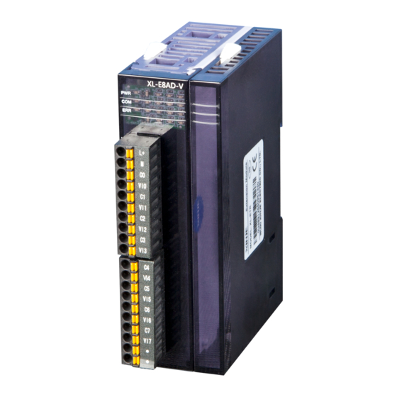
Xinje XL Series User Manual (195 pages)
PLC extension module
Brand:
Xinje
| Category:
Control Unit
| Size: 9 MB
Table of Contents
Table of Contents
3
Module Information Summary
6
Module Model and Configuration
6
Part Name and Function
7
Module Power and Usage Conditions
8
Module Installation
10
Wiring Requirement
12
Terminal Resistance Module Xl-Etr
13
I/O Extension Module Xl-Enxmy
15
Module Features and Specifications
15
Terminal Arrangement
17
Input Wiring and Specification
18
NPN Input Specification and Wiring
18
PNP Input Specification and Wiring
19
NPN&PNP Bipolar Input Specification and Wiring
20
Output Wiring and Specification
22
Wiring Head Specifications
24
External Terminal Block
24
I/Odefinition Number
25
Module Parameters
27
Dimension
31
Application
32
Hardware Connection
33
Program Application
33
Analog I/O Module Xl-E4Ad2Da
36
Module Features and Specifications
36
Terminal Description
37
I/Oaddress
38
Working Mode Settings
43
External Wiring
46
Analog Digital Conversion Diagram
48
Dimension
50
Application
50
Analog Input Module Xl-E8Ad-A
52
Module Features and Specifications
52
Terminal Descriptions
53
I/Oaddress
54
Working Mode Settings
59
External Wiring
62
Analog Digital Conversion Diagram
63
Dimension
63
Application
64
Analog Input Module Xl-E8Ad-V
65
Module Features and Specifications
65
Terminal Descriptions
66
I/Oaddress
67
Working Mode Settings
72
External Wiring
75
Analog Digital Conversion Diagram
76
Dimension
76
Application
77
Analog Output Module Xl-E4Da
78
Module Features and Specifications
78
Terminal Description
79
I/Oaddress
80
Working Mode Settings
84
External Wiring
86
Current Output
87
Analog Digital Conversion Diagram
87
Dimension
88
Application
89
Pt100 Temperature Module Xl-E4Pt3-P
90
Module Features and Specifications
90
Terminals
91
I/Oaddress
92
Working Mode
97
External Wiring
99
Dimension
101
Application
101
Thermocouple Temperature Module Xl-E4Tc-P
104
Specifications
104
Terminals
105
I/Owiring Example
107
I/Oaddress Assignment
108
From/To Instruction
109
Working Mode
112
Dimension
116
Programming Example
116
Analog Input Module Xl-E4Ad
119
Specifications
119
Terminals
120
I/Oaddress Assignment
120
Working Mode
124
Flash Registers
125
Exterior Connection
126
Ad Conversion Diagram
128
Dimension
129
Programming
129
N Channel Pressure Measurement Module Xl-Enwt-D
131
Features
131
Terminals
132
External Connection
134
Weighing System
135
Module Functions
136
Pressure Sensor
136
I/Oaddress
137
Working Mode
142
Module Setting
144
Module Error Info
146
Instruction from and to
146
Dimension
150
Application Program
151
Analog Input Module Xl-E8Ad-A-S
152
Module Features and Specifications
152
Terminal Descriptions
153
I/Oaddress
154
Working Mode Settings
160
External Wiring
163
Current Input
163
Analog Digital Conversion Diagram
164
Dimension
165
Application
165
Analog Input Module Xl-E8Ad-V-S
166
Module Features and Specifications
166
Terminal Descriptions
167
I/Oaddress
168
Working Mode Settings
174
External Wiring
177
Analog Digital Conversion Diagram
177
Dimension
178
Application
178
Pt100 Temperature Module Xl-E4Pt3-P-H
180
Module Features and Specifications
180
Terminals
182
I/Oaddress
183
Working Mode
187
External Wiring
190
Dimension
192
Application
192
Advertisement
Xinje XL Series User Manual (105 pages)
PLC extension module
Brand:
Xinje
| Category:
Control Unit
| Size: 2 MB
Table of Contents
Table of Contents
3
Module Information Summary
5
Module Model and Configuration
5
Dimension
6
Part Name and Function
8
General Specification
9
Module Installation
10
Configuration of the Module
12
Terminal Resistance Module Xl-Etr
13
I/O Extension Module Xl-Enxmy
15
Module Features and Specifications
15
Terminal Descriptions
16
I/Odefinition Number
17
External Connection
19
Module Parameters
22
Dimension
25
Application
26
Analog I/O Module Xl-E4Ad2Da
30
Module Features and Specifications
30
Terminal Description
31
I/Oaddress
32
Working Mode Settings
37
External Wiring
40
Analog Digital Conversion Diagram
42
Dimension
44
Application
44
Analog Input Module Xl-E8Ad-A
46
Module Features and Specifications
46
Terminal Descriptions
47
I/Oaddress
48
Working Mode Settings
53
External Wiring
56
Analog Digital Conversion Diagram
57
Dimension
57
Application
58
Analog Input Module Xl-E8Ad-V
58
Module Features and Specifications
59
Terminal Descriptions
59
I/Oaddress
61
Working Mode Settings
66
External Wiring
69
Analog Digital Conversion Diagram
69
Dimension
70
Application
70
Analog Output Module Xl-E4Da
71
Module Features and Specifications
72
Terminal Description
72
I/Oaddress
74
Working Mode Settings
77
External Wiring
80
Nalog Digital Conversion Diagram
81
Dimension
82
Application
82
Pt100 Temperature Module Xl-E4Pt3-P
83
Module Features and Specifications
83
Terminals
84
I/Oaddress
86
Working Mode
88
External Wiring
90
Dimension
91
Application
92
Terminals
97
I/Oaddress Assignment
97
Working Mode
100
External Connection
101
Dimension
102
Programming Example
103
Xinje XL Series Manual (2 pages)
Brand:
Xinje
| Category:
Network Hardware
| Size: 1 MB
Advertisement
Related Products
Xinje XC1-10R-E
Xinje XC1-16T-C
Xinje XC1-24PT-C
Xinje XC1-32PT-C
Xinje XC2-16R-C
Xinje XC2-16T-C
Xinje XC2-32RT-C
Xinje XC2-60RT-E
Xinje XC2-14PT-C
Xinje XP1-18R
Xinje Categories
Servo Drives
Control Unit
Controller
Computer Hardware
Network Hardware
More Xinje Manuals
Login
Sign In
OR
Sign in with Facebook
Sign in with Google
Upload manual
Upload from disk
Upload from URL