
Related Manuals for INVT XG25-40KTR


Summary of Contents for INVT XG25-40KTR
- Page 1 User Manual XG25-40KTR Grid-tied Solar Inverter INVT Solar Technology (Shenzhen) Co., Ltd.
- Page 2 Preface The manual is intended to provide detailed information of product information, installation, application, trouble shooting, precautions and maintenance of iMars series grid-tied solar inverters. The manual does not contain all the information of solar system. Please read this manual carefully and follow all safety precautions seriously before any moving, installation, operation and maintenance to ensure correct use and high performance of operation on the inverter.
-
Page 3: Table Of Contents
Grid-tied three-phase solar inverter Contents Content Preface ................................i Content ................................ii 1 Safety precautions ............................. 1 1.1 Warning marks .............................1 1.2 Safety guidance ...........................1 1.2.1 Transport and installation ......................3 1.2.2 Grid-tied operation ........................3 1.2.3 Maintenance and inspection .......................4 1.2.4 Waste disposal ..........................4 2 Product overview ............................ - Page 4 Grid-tied three-phase solar inverter Contents 5.1 Overview of electrical connection ..................... 20 5.2 Connect the protective earth wire .....................20 5.3 Connection of solar string ......................... 21 5.4 Three-phase inverter grid connection ....................22 5.4.1 Grid connection .........................23 5.4.2 Parallel operation requirements ....................24 6 Running ..............................
-
Page 5: Safety Precautions
Grid-tied three-phase solar inverter Safety precautions 1 Safety precautions iMars series grid-tied solar inverters are designed and tested strictly in accordance with relevant international safety standards. As an electrical and electronic device, all relevant safety regulations must be strictly complied during installation, operation, and maintenance. Incorrect use or misuse may result in: Injury to the life and personal safety of the operator or other people. - Page 6 Grid-tied three-phase solar inverter Safety precautions technicians who have received professional trainings and thoroughly familiar with all the contents in this manual and the safety requirements of the electrical system. Do not carry out cable connection/disconnection, cover open for inspection and ...
-
Page 7: Transport And Installation
Grid-tied three-phase solar inverter Safety precautions 1.2.1 Transport and installation During storage or transport, ensure the inverter package and the chassis is intact, dry and clean. The movement and installation of the inverter require at least two persons due to ... -
Page 8: Maintenance And Inspection
Grid-tied three-phase solar inverter Safety precautions 1.2.3 Maintenance and inspection The maintenance, inspection and repair of the inverter must be done by well trained and qualified professional technicians. Contact distributor or manufacture for inverter repairing. In order to avoid irrelevant personnel entering the maintenance area during ... -
Page 9: Product Overview
Grid-tied three-phase solar inverter Product overview 2 Product overview This chapter mainly describes the appearance, package accessories, nameplate and technical parameters of the grid-tied inverter. 2.1 Grid-tied PV power generation system Grid-tied PV power generation system comprises solar panels, grid-tied inverter, energy meter and power grid. -
Page 10: Product Appearance
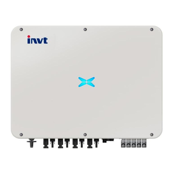
Grid-tied three-phase solar inverter Product overview 2.2 Product appearance Fig 2.3 Appearance of the three-phase PV inverter Table 2-1 Instruction list Name Instructions DC switch Switch on or off DC input DC input connectors DC input port, connect to PV array Communication interfaces USB, RS485, DRM communication terminals AC connector... -
Page 11: Nameplate
Grid-tied three-phase solar inverter Product overview 2.3 Nameplate Figure 2.4 shows the inverter nameplate. Fig 2.4 Inverter nameplate (1)Trademark and product type (2)Model and important technical parameters (3) Certification systems which the inverter conforms, serial number, company name and country of origin... -
Page 12: Product Model
Grid-tied three-phase solar inverter Product overview Icons Instruction TUV certification mark. The inverter is certified by TUV. CE certification mark. The inverter complies with the CE directive. CQC certification mark. The inverter passed CQC certification. EU WEEE mark. The inverter cannot be disposed of as domestic waste. ... -
Page 13: Outline Dimension And Weight
Grid-tied three-phase solar inverter Product overview 2.5 Outline dimension and weight Fig 2.5 Dimensions of the inverter Table 2-3 Dimensions and weight Model Height (mm) Width (mm) Depth (mm) Net weight (kg) 25-40kW 37.5 Fig 2.6 Dimension of carton box Table 2-4 Package dimension and gross weight Package Model... -
Page 14: The Front Panel
Grid-tied three-phase solar inverter Product overview 2.6 The front panel The front panel comes with LED indicators (modern design) or LCD panel a to indicate the working state of the inverter. 2.6.1 LED panel (Modern design) LED indication: Steady blue Normal, grid-tied and generating power Bluetooth connected and with Blinking blue at short... -
Page 15: Lcd Panel
② Alarm indicator, yellow, indicates alarm state; ③ Fault indicator, red, indicates fault state; ④UP button, for up selection; ⑤Down button, for down selection. 2.7 Bottom of chassis XG25-40KTR is equipped with one DC switch, which connects or disconnects all PV inputs. XG25-40KTR bottom view... -
Page 16: Storage
Grid-tied three-phase solar inverter Storage 3 Storage If the inverter is not put into use immediately, the storage of inverter should meet the following requirements: Do not remove the outer packing. The inverter needs to be stored in a clean and dry place, and prevent the erosion of dust and water vapor. -
Page 17: Installation
Confirm the deliverables inside the package box are intact and complete; Check whether the product information in the order is consistent with that on the inverter nameplate; The standard delivery list is shown below. Standard deliverables of three-phase inverter: Fig 4.1 Deliverables of XG25-40KTR three-phase inverter... -
Page 18: Preparation Before Installation
Grid-tied three-phase solar inverter Installation Table 4-1 Deliverables of three-phase inverter Name Inverter Installation bracket Water-proof cover for AC output RS-485 communication cable DC connector (pair) 6/8* Operation manual Expansion bolt (M84*60) Nuts and bolts (M8) Bolts (M4) AC ring connector *XG25KTR/XG30KTR/XG33KTR 6 pairs * XG36KTR/XG40KTR 8 pair Check above items carefully and if any question, contact the supplier immediately. -
Page 19: Installation Environment
Grid-tied three-phase solar inverter Installation 4.2.2 Installation environment (1) The inverter can be installed in indoor and outdoor environment. (2) During the operation of the inverter, the temperature of the chassis and heat sink will be relatively high. Please do not install the inverter in the easily touched position. (3) Do not install inverters in areas where flammable and explosive materials are stored (4) The inverter shall be installed in a place which has good ventilation to ensure good heat dissipation... - Page 20 Grid-tied three-phase solar inverter Installation Fig 4.3 optimal installation height (2) Make sure there is enough space for installation and ventilation, see below recommendations. Fig 4.4 installation spacing of inverter (3) When installing multiple inverters, a certain distance should be reserved between the inverters, as shown in Figure 4.4.
-
Page 21: Dimensions Of The Mounting Bracket
Grid-tied three-phase solar inverter Installation (4) Install the inverter vertically or lay back a little bit (≤15°) for good heat dissipation. Do not tilt the inverter forward, horizontally, upside down, over-backward or roll it. Fig 4.6 installation posture of inverter 4.4 Dimensions of the mounting bracket Fig 4.6 dimensions of mounting bracket 4.5 Wall installation... -
Page 22: Installation Of Inverter
Grid-tied three-phase solar inverter Installation Step 2:Drill holes on the wall for the M8 x 60 expansion bolts with impact drill. Step 3:Clean the dust out from the holes and knock the screw and expansion tube of the expansion bolts into the holes with a rubber hammer. Put the bracket, flat pads, spring pads and nuts in turn onto the bolts. - Page 23 Grid-tied three-phase solar inverter Installation Step 3: Hang the inverter onto the bracket and make sure the hanging is in place. Step 4: Fix the inverter and the bracket with one M4 x 12 screw on the left side of the inverter with 2.5N•m, see below.
-
Page 24: Electrical Connection
Grid-tied three-phase solar inverter Electrical connection 5 Electrical connection 5.1 Overview of electrical connection This section presents the detailed contents and safety precautions related to electrical connection. Fig 5.1 is the connection diagram for Grid-tied PV system. Fig 5.1 Connection diagram of the Grid-tied PV system Electrical connection must be carried out by professional technicians as wrong ... -
Page 25: Connection Of Solar String
Grid-tied three-phase solar inverter Electrical connection 5.3 Connection of solar string Step 1: Make MC4 connectors for each PV string MC4 crimping method: Remove 8-10mm cable sheath from the PV cable (see A and B below), crimp the inner contact of MC4 connector with the cable(see C below, the longer one is for positive PV wire);... -
Page 26: Three-Phase Inverter Grid Connection
Grid-tied three-phase solar inverter Electrical connection Fig 5.3 DC input polarity and voltage check Use the DC connectors delivered along with the inverter, do not use other connectors without authorization from our company, otherwise damage to the device, unstable operation or fire may occur and our company will not undertake quality assurance or assume any direct or joint liability thereof. -
Page 27: Grid Connection
Grid-tied three-phase solar inverter Electrical connection 5.4.1 Grid connection (1) Crimp ring connectors on the AC cable for the Grid, the N of the five cores (L1, L2, L3, N, PE) is optional. It is very important that the crimping is tight and reliable; Fig 5.5 crimping cable terminals (2) Connect the crimped AC cable to the AC block of the inverter with 7-9N•m (PE) and connect the AC water-proof cover. -
Page 28: Parallel Operation Requirements
Grid-tied three-phase solar inverter Electrical connection 5.4.2 Parallel operation requirements Multiple inverters can be connected to the low-voltage three-phase grid directly, contact us if the total capacity of the inverters exceeds 0.5-0.8MVA. If the Grid is not low-voltage, a step-up transformer should be used. Connect the inverters to the low voltage side of transformer. -
Page 29: Running
Grid-tied three-phase solar inverter Running 6 Running This chapter mainly introduces inverter operations related to inspection before running, power generation, stop power generation and maintenance. 6.1 Inspection before running The following items must be checked strictly before running the Grid-tied PV inverter (including but not limited to the following items): (1) Confirm the installation site of the inverter meet requirements of section 4.2.2 to ensure convenient installation, disassemble, operation and inspection on the inverter;... -
Page 30: Inverter Stop
Grid-tied three-phase solar inverter Running Running LED is solid green (the other two LEDs are off): Inverter self-checking passed, generation power to the Grid. ‘Alarm’ or ‘Fault’ is on or blinks: Inverter powered on but has errors. Check on the LCD and look up the codes on Table 8-1 for the definition of the codes. -
Page 31: Maintenance Guidance
Grid-tied three-phase solar inverter Running Inspection Maintenance Inspection method item cycle especially where it is close to the metal. Check if the air intake and exhaust are normal, check if the fan has abnormal running noise and if its blades have Once per half a Cooling fan cracks. - Page 32 Grid-tied three-phase solar inverter Running Step 2: Unscrew the screws as below, unplug the fan cables and remove the fan plate at the bottom. Step 3: Clean the fan with dusting brush or vacuum cleaner, change it if the fan has been damaged (refer to below Step 4).
-
Page 33: Lcd Display Operation
Grid-tied three-phase solar inverter LCD display operation 7 LCD display operation This chapter describes the LCD operation and LED indicators. -
Page 34: Troubleshooting
Troubleshooting Grid-tied three-phase solar inverter 8 Troubleshooting This chapter describes the error codes for fast troubleshooting. Table 8-1 Inverter error codes Descriptions Code Descriptions (long) Troubleshooting tips (short) A001 Input UV Input under-voltage PV under-voltage A002 Bus UV Bus under-voltage PV under-voltage or boost circuit fail A003 Grid UV... - Page 35 Troubleshooting Grid-tied three-phase solar inverter Descriptions Code Descriptions (long) Troubleshooting tips (short) communication error cannot communicate with each other or the data check failed Leakage current is too System/inverter leakage current is E010 ILeek Fail high too high E011 Relay Fault Relay fault Inverter internal relay has fault E012...
- Page 36 Troubleshooting Grid-tied three-phase solar inverter If any problem, please contact with the supplier and provide following information: Model of the inverter: Serial No. of the inverter: System version: ——version 1: ——version 2: ——MCU software version: Fault code: Fault description ...
-
Page 37: Contact Us
Three-phase photovoltaic grid-tied inverter Contact 9 Contact us China·Shenzhen INVT Solar Technology (Shenzhen) Co., Ltd. Address: 6th Floor, Block A, INVT Guangming Technology Building, Songbai Road, Matian, Guangming District, Shenzhen, China Service hotline: +86 400 700 999 E-mail: solar-service@invt.com.cn INVT group website: www.invt.com... -
Page 38: Appendix
Grid-tied three-phase solar inverter Appendix 10 Appendix Table 9-1 Datasheet Model XG25KTR-3M XG30KTR XG33KTR XG36KTR XG40KTR Max. DC voltage (V) 1100 1100 1100 1100 1100 Start-up voltage (V) MPPT voltage range (V) 200~1000 200~1000 200~1000 200~1000 200~1000 DC voltage range during rated 450-800V 500-800V 500-800V... - Page 39 Grid-tied three-phase solar inverter Appendix Table 9-2 Datasheet Model XG25KTR-3S XG30KTR-S XG33KTR-S XG36KTR-S XG40KTR-S Max. DC voltage (V) 1100 1100 1100 1100 1100 Start-up voltage (V) MPPT voltage range (V) 200~1000 200~1000 200~1000 200~1000 200~1000 DC voltage range during rated 500-800V 500-800V 500-800V...
Need help?
Do you have a question about the XG25-40KTR and is the answer not in the manual?
Questions and answers
Bonjour j'ai un problème avec le nouveau INVT XG30KTR , nous n'arrivons pas à le démarrer il affiche sur le tableau RUNNING error; F 31-03; GIRD EN 50549 , qu'est ce qu'on doit faire?
To resolve the RUNNING error F 31-03 on the INVT XG30KTR inverter:
1. Check the LCD for the fault code and refer to Table 8-1 for its definition.
2. Stop the inverter:
- Disconnect the AC breaker to isolate the inverter from the grid.
- Turn off the built-in DC switch of the inverter.
- Turn off the external DC breaker to disconnect the PV strings.
- Wait at least 5 minutes for internal discharge.
3. Refer to the troubleshooting section (Section 8) to identify and fix the cause of the fault.
4. After clearing the fault, follow Section 5 to reconnect and restart the inverter.
This answer is automatically generated