Advertisement
Table of Contents
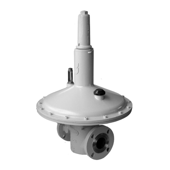
J123
Commissioning Instructions
Fig. 1
Fig. 2
Fig. 3
Fig. 4
Fig. 5
INSTALLATION CONDITIONS
Body pressure range: 0 - 4 Bar
Temperature range: -20ºC to +70 ºC
OPERATING INSTRUCTIONS
•
Ensure that this product is suitable for the chosen application.
•
Installation, adjustment and maintenance by authorised, trained personnel only.
•
When being fitted to an appliance, refer to the appliance manufacturers instructions.
•
Ensure that the installation provides adequate protection to prevent over pressurisation.
•
Traffic, wind and earthquake loadings should be considered when specifying the installation.
•
The unit should be protected from the decomposition of unstable fluids.
Warning!
Incorrect installation, adjustment, modification, operation and maintenance may
cause injury or damage.
Read the instructions before use. This control must be installed in accordance with the rules in
force.
FITTING UNITS INTO PIPEWORK
1.
The unit should not be installed in a corrosive environment.
2.
The ambient temperature (surface temperature) should be within the limits stated on the
regulator catalogue.
3.
Check the maximum allowable pressure on the regulator nameplate against the installation
specification.
4.
Remove the protection from the inlet and outlet ports.
5.
Ensure that the installation pipework is thoroughly clean.
6.
The direction of gas flow must be the same as the arrows on the regulator body. See Fig. 1.
7.
Install regulator into pipework.
8.
It is advised that a slam shut device is fitted in the installation to protect downstream equipment.
INSTALLATION OF IMPULSE LINE
1.
Remove the plastic protection plug.
2.
Connect the impulse line (½"), using a jointing compound approved to national standards, and
lead to a point downstream not less than fifteen times the nominal pipe diameter from the
outlet. See Fig. 2.
INSTALLATION OF VENT LINE. (If Required)
1.
Remove breather cover from regulator top case / cover.
2.
Connect the vent line (½"), using a jointing compound approved to national standards, and lead
to atmosphere in accordance with national standards. Ensure that no water can penetrate vent
pipe. See Fig. 3.
3.
If vent connection is to be used for top loading or other similar use refer to your own installation
instructions.
SETTING THE OUTLET PRESSURE.
1.
Turn off inlet and outlet valves.
2.
Remove top cap.
3.
For L.P. 50mm and 80mm unit insert ½" square socket extension piece into square hole, or flat
blade screwdriver into slot in spring adjuster. See Fig. 4.
4.
For M.P. 50mm and 80mm unit, slacken locknut on spring adjusting stem and connect suitable
spanner (24mm A/F) to hexagon of spring adjusting stem. See Fig. 5.
5.
For 100mm unit connect suitable spanner (27mm A/F) to hexagon of spring adjusting nut. See
Fig. 6.
6.
Turn spring adjustment anticlockwise to reduce pressure on loading spring.
7.
Slowly turn on inlet supply.
8.
Increase loading on spring by turning spring adjustment clockwise until the required outlet
pressure, plus approximately 2.5mbar, is obtained.
9.
Commission downstream appliance(s).
10.
Trim the outlet pressure of the regulator, if necessary, when normal
working flow rates have been achieved.
11.
Replace the top cap.
Advertisement
Table of Contents

Related Manuals for Elster J123


Summary of Contents for Elster J123
- Page 1 J123 Commissioning Instructions INSTALLATION CONDITIONS Body pressure range: 0 - 4 Bar Temperature range: -20ºC to +70 ºC OPERATING INSTRUCTIONS • Ensure that this product is suitable for the chosen application. • Installation, adjustment and maintenance by authorised, trained personnel only.
- Page 2 J123: Commissioning Instructions IF THE REQUIRED OUTLET PRESSURE CAN NOT BE ACHIEVED WITH THE SPRING FITTED. Choose a loading spring from the catalogue that will give the required outlet pressure range. For L.P. 50mm and 80mm units: See Fig. 7.
Need help?
Do you have a question about the J123 and is the answer not in the manual?
Questions and answers