Table of Contents
Advertisement
Quick Links
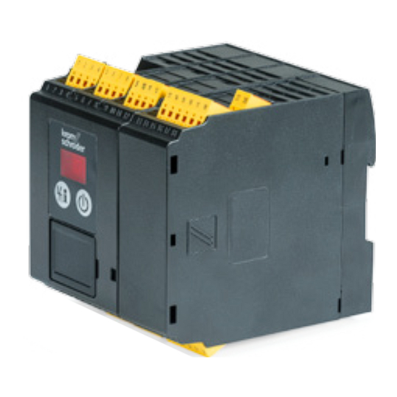
Burner control units BCU 580
Technical Information · GB
6 Edition 11.15
• For monitoring and controlling modulating or staged burners for multiple
burner applications with a central air supply
• For directly ignited burners or burners ignited by a pilot burner in intermittent
or continuous operation
• Optionally with valve proving system
• Flexible range of applications due to parameterization possibilities
• PROFINET fieldbus connection using optional bus module
• Assume safety functions pursuant to EN 746-2
• EC type-tested and certified
• Safety functions up to SIL 3 (DIN EN 62061)
corresponding to PL e (ISO EN 13849)
Advertisement
Table of Contents

Related Manuals for Elster BCU 580


Summary of Contents for Elster BCU 580
-
Page 1: Burner Control Units Bcu 580
Burner control units BCU 580 Technical Information · GB 6 Edition 11.15 • For monitoring and controlling modulating or staged burners for multiple burner applications with a central air supply • For directly ignited burners or burners ignited by a pilot burner in intermittent or continuous operation • Optionally with valve proving system... -
Page 2: Table Of Contents
Burner control units BCU 580 . . . . . . . . . . . . . . . . . . - Page 3 19 Glossary . . . . . . . . . . . . . . . . . . . . . . . . . . . . . . . . . . . . 120 ▼ = To be continued BCU 580 · Edition 11.15...
- Page 4 Contact . . . . . . . . . . . . . . . . . . . . . . . . . . . . . . . . . . . . . . . 123 ▼ = To be continued BCU 580 · Edition 11.15...
-
Page 5: Application
Burner control unit with plug-in spring force connection terminals a new BCU to transfer the parameters, for example when replacing the unit. Burner control unit BCU 580 controls, ignites and monitors gas burners in intermittent or continuous operation. It can be used ▼... - Page 6 DIN rail installation. It is pushed on to the BCU from the side. Thanks to the operator-control unit OCU, display functions and op- eration of the BCU can be relocated to the control cabinet door. BCU 580 · Edition 11.15...
- Page 7 Application Bogie hearth forging furnace in the metal- Intermittent shuttle kiln in the ceramics Walking beam furnace with overhead firing lurgical industry industry BCU 580 · Edition 11.15...
-
Page 8: Examples Of Application
ϑ1 ϑ2 The UV sensor monitors the flame signal TZI/TGI from pilot and main burners. The BCU provides the cooling and purg- BCU 580..C0F3 ing processes. µC VR..L 02–04 06–08 02–04 06–08 ϑ1 ϑ2 BCU 580 · Edition 11.15... -
Page 9: Stage-Controlled Main Burner With Permanent Pilot Burner
Process control (PCC) the time required by the main burner FCU 500 for starting up. The BCU provides the cooling and purg- ing processes. ϑ1 ϑ2 TZI/TGI BCU 580..C0F3 µC VR..L 02–04 06–08 06–08 ϑ1 ϑ2 BCU 580 · Edition 11.15... -
Page 10: Two-Stage-Controlled Main Burner With Permanent Pilot
The BCU provides the cooling and purg- ing processes. ϑ1 ϑ2 TZI/TGI BCU 580..C0F2 µC 53 55 51 52 µC IC 40 + BVA 02–04 06–08 06–08 ϑ1 ϑ2 BCU 580 · Edition 11.15... -
Page 11: Modulating-Controlled Burner
TZI/TGI This reduces the time required by the ϑ1 ϑ2 main burner for starting up. BCU 580..C0F1 µC 53 54 55 IC 20 + BVA 02–04 06–08 06–08 ϑ1 ϑ2 BCU 580 · Edition 11.15... -
Page 12: Flame Control Using The Temperature
If the furnace temperature falls below the spontaneous igni- tion temperature (< 750°C), the FCU disconnects the HT output from the electrical power supply. As soon as the signal to the HT inputs of the burner control units is no longer present, the BCU 580 · Edition 11.15... -
Page 13: Profinet Connection Using Bus Module Bcm
Control signals that are relevant for safety, such as the safety interlocks, purge and HT input, are transferred independently of the bus communication by separate cables. BCU 580 · Edition 11.15... -
Page 14: On/Off Rotary Impulse Control
BCU 580. VR..L The centrally checked safety functions such as pre-purge, tightness test, flow detector and pressure switch check (gas- , gas , air ) are provided by the min. max. min. FCU 500. BCU 580 · Edition 11.15... -
Page 15: Modulating Burner Control
90° 0° The centrally checked safety functions 47 48 such as pre-purge, tightness test, flow Purge detector and pressure switch check (gas- , gas , air ) are provided by the min. max. min. FCU 500. VR..L BCU 580 · Edition 11.15... -
Page 16: Certification
Factory Mutual Research Class: 7400 Process Control Valves. Designed for applications pursuant to NFPA 85 and NFPA 86. www.approvalguide.com ANSI/CSA approved American National Standards Institute/Canadian Stand- ards Association – ANSI Z21.20/CSA C22.2 No. 199 www.csagroup.org – Class number: 3335-01 and 3335-81. BCU 580 · Edition 11.15... -
Page 17: Function
Alternative flame control, see page 20 (Flame control). ϑ1 62 61 5 6 7 8 11 12 ϑ2 max. 1 A; 24 V DC, 250 V AC 3,15AT µC BCU 580..F1 0.6 × I +24 V (P40 = 2/3) => 51 BCU 580 · Edition 11.15... -
Page 18: Bcu 580
ϑ2 max. 1 A; max. 1 A; 24 V DC, 24 V DC, 250 V AC 250 V AC Luft 3,15AT 3,15AT Luft (P69 = 13) AUTO µC BCU 580..F2 0,6 × I +24 V BCU 580 · Edition 11.15... -
Page 19: Bcu 580
Explanation of symbols, see page 119 (Legend) ϑ1 62 61 5 6 7 8 11 12 ϑ2 max. 1 A; 24 V DC, 250 V AC 3,15AT µC BCU 580..F3 0.6 × I +24 V BCU 580 · Edition 11.15... -
Page 20: Flame Control
(P40 = 2/3) => 51 62 61 5 6 7 8 11 12 ϑ2 µC max. 24 V D 250 V A BCU 580..F1 µC 3,15AT +24 V (P40 = 2/3) => 51 BCU 580..F1 BCU 580 · Edition 11.15... -
Page 21: Bcu 580 Program Sequence
Function 3 .2 BCU 580 program sequence Flame proving period 1 t running (P95) Parameters 48 and 49 = 0: High/Low control during operation, ▼ cooling in standby In the event of flame failure: fault lock-out Example of application, see page 10 (Two-stage-controlled main burner with permanent pilot burner) ▼... - Page 22 Function > BCU 580 program sequence Main burner operation signalling contact closes, minimum operating time t starts (P61) ▼ In the event of flame failure: restart or fault lock-out ▼ External actuation of the air valve for capacity control 08 Controlled shut-down via ϑ signals for pilot and main burners ▼...
-
Page 23: Air Control
The capacity is controlled during operation by an external temperature control system. BCU 580..F3 BCU 580..F3 ϑ ϑ VR..L VR..L µC µC BCU 580..F3 BCU 580..F3 >750° >750° FCU 500..F0 FCU 500..F0 47 48 47 48 Purge Purge VR..L VR..L BCU 580 · Edition 11.15... -
Page 24: Capacity Control
(Air actuator control). As soon as there is a purge signal at terminal 50 of BCU..F1/ F2, the control element is activated by the outputs for capacity control to approach the position for pre-purge. The protec- BCU 580 · Edition 11.15... -
Page 25: Bcu
Once the protective system (terminal 46, safety interlocks) has issued the enable signal, the burner can be started by the start-up signal at terminal 1. The gas valves for the 1 stage are opened and the burner is BCU 580 · Edition 11.15... -
Page 26: Valve Proving System
European standards EN 746-2 and EN 676 stipulate tightness controls for capacities over 1200 kW (NFPA 86: from 117 kW or 400,000 Btu/h). The tightness control function satisfies the requirements of EN 1643, EN 746-2, ISO 13577-2 and NFPA 86 for valve prov- ing systems. BCU 580 · Edition 11.15... -
Page 27: Test Instant
An additional bypass/relief valve must be installed in gas sections with an air/gas ratio control. This ensures that the test volume V can be vented during the tightness test with the air/gas ratio control closed. BCU 580 · Edition 11.15... -
Page 28: Program Sequence
V2 is around atmospheric pressure and the volume downstream of V2 is at least 5 × higher than the volume t M = P56 t M = P56 between the valves. – ▼ p Z > p Z > – BCU 580 · Edition 11.15... - Page 29 – p Z > p Z > between the valves. – t L = P59 t L = P59 t M = P56 t M = P56 – p Z > p Z > – BCU 580 · Edition 11.15...
-
Page 30: Test Period T P
1000 x 1 [m justed for each individual system by adapting the measure- ment time t . The longer the measurement time t , the greater the sensitivity of the tightness control. The measurement time ▼ Test volume V BCU 580 · Edition 11.15... - Page 31 0.01 VG 15 0.07 VG 20 0.12 12.3 VG 25 17.7 VG 40/VK 40 31.4 VG 50/VK 50 VG 65/VK 65 VG 80/VK 80 VK 100 VK 125 13.6 VK 150 VK 200 VK 250 BCU 580 · Edition 11.15...
- Page 32 200 m /h x 1000 l/h Leakage = 200 l/h rate Q 1000 x 1 m Test volume V = 1.1 l + 9.5 m x 3.3 l/m = 32.45 l see page 30 (Test volume Vp1) BCU 580 · Edition 11.15...
-
Page 33: Proof Of Closure Function
POC switch. If a signal is still re- ceived at terminal 45 from the POC switch after a timeout time of 10 s, the BCU performs a fault lock-out with fault message c8. BCU 580 · Edition 11.15... -
Page 34: Bcsoft
In addition, BCSoft provides extended access to the individual statistics and protocol functions. In addition to the engineering tool BCSoft, an opto-adapter or Bluetooth adapter is required to read the device parameters in and out, see also page 106 (BCSoft). BCU 580 · Edition 11.15... -
Page 35: Profinet
IO devices start up or sending a diag- nostic message from the IO device to the IO controller during operation. The data read or written acyclically by read/write BCU 580 · Edition 11.15... -
Page 36: Bcu And Bus Module Bcm
Profinet use. For information on planning and the structure of a Profibus network and the components to be used (e.g. cables, lines and switches), see Profinet Installation Guide at www.profibus.com. BCU 580 · Edition 11.15... -
Page 37: Gsd File For Plc Configuration
The steps required to integrate the file are described in the instructions for the engineering tool for your automation system. For parameter settings on the BCU and code switch settings on the BCM, see page 96 (Fieldbus communication). BCU 580 · Edition 11.15... -
Page 38: Modules For Cyclic Data Exchange
Fault and warning signals n...n+1 Remaining times n...n+1 TC remaining times n...n+1 PLC output information BCU input terminal information n...n+2 BCU output terminal information n...n+1 Only for BCU..C1. Slot 7 is not transferred with other device versions. ▼ BCU 580 · Edition 11.15... -
Page 39: Safety Shut-Down
Burner 1 flame Parallel to the bus communication, terminals 1 to 4 can be Manual mode Free BOOL signal wired. Only with three-point step control via bus. Only with three-point step control via bus. ▼ BCU 580 · Edition 11.15... - Page 40 PLC as an analogue value using this module. The flame signal occupies one byte with values from 0 to 255 (= flame signal from 0 to 25.5 µA). Bit Byte n Data type Format Value Burner 2 flame 0 – 255 Byte signal (0 – 25.5 μA) BCU 580 · Edition 11.15...
- Page 41 0 – 255 (see ▼ Code table Fault signals Byte “GSD_Codes_ BCU580.xlsx” at www.docuthek.com) Data Bit Byte n+1 Format Value type 0 – 255 (see Code table Warning signals Byte “GSD_Codes_ BCU580.xlsx” at www.docuthek.com) BCU 580 · Edition 11.15...
- Page 42 6 Open control element, three-point step Open BOOL 7 Close control element, three-point step Close BOOL Only with three-point step control via bus. Remaining times 0 – 6554 ▼ of the valve prov- Word (0 – 6554 s) ing system BCU 580 · Edition 11.15...
- Page 43 4 Terminal 15 Terminal 55 BOOL 5 Terminal 17/18 Terminal 56 BOOL 6 Terminal 37/38 Terminal 57 BOOL 7 Terminal 41 Free BOOL Only for BCU..F2: terminal 53 is used as an input. Bit 6 has no function. BCU 580 · Edition 11.15...
-
Page 44: Indexes For Acyclic Communication
1004 Operator statistics, counter 1005 Operator statistics, faults/warnings 1006 Fault history 1007 Power module statistics The contents and description of the indexes are described in the code table “GSD Codes BCU 580” (download from www. docuthek.com). BCU 580 · Edition 11.15... -
Page 45: Program Step/Status
Safety time 1 Delay Flame proving period 1 t Flame proving period 1 t Burner 1 operation Burner 1 operation Delay Delay Safety time 2 Safety time 2 Flame proving period 2 Flame proving period 2 ▼ BCU 580 · Edition 11.15... - Page 46 Program step/status Burner 2 operation Burner 2 operation Delay Remote control with OCU Data transfer (programming mode) – – Device Off In Manual mode, two dots blink on the display. Air actuator (control element/valve) is open. BCU 580 · Edition 11.15...
-
Page 47: Fault Signalling
NFS parameter range is inconsistent Fail-safe parameters (FS) inconsistent FS parameter range is inconsistent Mains voltage Operating voltage too high/low Faulty parameterization Parameter set contains illegal settings Incompatible bus module Power module defective Relay contact error ▼ BCU 580 · Edition 11.15... - Page 48 Ignition capacity not reached Position for ignition capacity has not been reached after 255 s Communication with bus module Bus module fault Parameter chip card (PCC) Incorrect or defective PCC POC valve open Valve not closed ▼ BCU 580 · Edition 11.15...
- Page 49 No flame during safety time 2 while air valve open Flame failure during flame proving period 2 Flame failure during flame proving period 2 while air valve open Flame failure during burner 2 operation Flame failure during burner 2 operation while air valve open BCU 580 · Edition 11.15...
-
Page 50: Parameters
Intermittent operation with UVS Continuous operation with ionization/UVD 1 start-up attempt Burner 1 start-up attempts 2 start-up attempts 3 start-up attempts 1 start-up attempt Burner 2 start-up attempts 2 start-up attempts 3 start-up attempts ▼ BCU 580 · Edition 11.15... - Page 51 On; for approaching the position for maxi- mum capacity On; for approaching the position for mini- mum capacity Running time in seconds Running time 0 – 250 if parameter 41 = 1, 2 or 3 ▼ BCU 580 · Edition 11.15...
- Page 52 Air actuator in the event of fault Can be activated externally Tightness test before start-up Tightness test after shut-down Valve proving system Tightness test before start-up and after shut-down Proof of closure function Relief valve (VPS) ▼ BCU 580 · Edition 11.15...
- Page 53 LDS ignition position check AND with emergency stop (trm. 46) Function of terminal 67 Multi-flame control (MFC) start-up condi- tions AND with emergency stop (trm. 46) Function of terminal 68 Multi-flame control (MFC) operating condi- tions ▼ BCU 580 · Edition 11.15...
- Page 54 Time in seconds Flame proving period 1 tFS1 0 – 20 Time in seconds Safety time 2 tSA2 2, 3, 5, 10 Time in seconds Flame proving period 2 tFS2 0 – 20 Time in seconds BCU 580 · Edition 11.15...
-
Page 55: Scanning The Parameters
The sensitivity at which the burner control unit detects a flame at burner 2 can be set using parameter 02. In the case of UV control, this value can be increased, should the burner to be monitored be influenced by other burners for example. BCU 580 · Edition 11.15... -
Page 56: Flame Control
UV sensor for intermittent operation For intermittent operation, the operating state of the complete system is limited to 24 h pursuant to EN 298. To meet the re- quirement for intermittent operation, the burner is shut down BCU 580 · Edition 11.15... -
Page 57: High Temperature Operation
Only if the temperature at the furnace wall has exceeded 750°C may voltage be applied to the HT input (terminal 49) FCU 500..H1 so as to activate High temperature mode. BCU 580..D µC ϑ1 BCU 580..D ϑ2 µC ▼ BCU 580 · Edition 11.15... - Page 58 UV control with UVD). ϑ2 ▼ The BCU switches off the burner once the HT input has been disconnected from the electrical power supply and restarts with flame simulation check (recommended in the case of UV control with UVS). BCU 580 · Edition 11.15...
- Page 59 Parameters > Flame control > High temperature operation If no flame signal is present when High temperature mode is deactivated, the burner control unit performs a fault lock-out, regardless of parameter 06. Fault, pilot burner ϑ1 ϑ2 Fault, main burner ϑ1 ϑ2 BCU 580 · Edition 11.15...
-
Page 60: Behaviour During Start-Up
BCU safety shut-down with subsequent fault lock-out. The fault message 04 will flash in the BCU display depending on the burner operating mode. BCU 580 · Edition 11.15... -
Page 61: Burner 2 Start-Up Attempts
BCU safety shut-down with subsequent fault lock-out. The fault message 06 will flash in the BCU display depending on the burner operating mode. BCU 580 · Edition 11.15... -
Page 62: Burner Application
(P95) is set to a value ≥ 2 s. the burner in order to release the gas supply to the burner. 14 15 BCU 570 14 15 µC BCU 570 µC 47 48 47 48 17-18 17-18 ▼ BCU 580 · Edition 11.15... - Page 63 The burner is started with a limited ignition capacity using gas valve V3. After the elapse of the safety time t (program step 06), valve V2 opens (terminal 14). Pilot gas valve V3 is closed again after the elapse of the flame proving period t (program step 07). BCU 580 · Edition 11.15...
- Page 64 Valve V2 (terminal 14) can be opened with the valve V2. operating signal (program step 08) in order to operate burner 2 at maximum capacity. 14 15 14 15 57 BCU 570 BCU 570..C1F1 µC µC H5 06 47 48 47 48 17-18 17-18 BCU 580 · Edition 11.15...
-
Page 65: Safety Time 1 T
The burner application and the burner capacity are the main criteria for this. If the ϑ1 signal (terminal 1) drops out during safety time 1, the valves will not be switched off until the end of safety time 1. BCU 580 · Edition 11.15... -
Page 66: Safety Time 2 T
The burner application and the burner capacity are the main criteria for this. If the ϑ1 signal (terminal 1) drops out during safety time 2, the valves will not be switched off until the end of safety time 2. BCU 580 · Edition 11.15... -
Page 67: Behaviour During Operation
Parameter 09 = 0: Off. message. ▼ ϑ A safety shut-down with subsequent fault lock-out takes place in the event of flame failure during operation. Parameter 09 = 1: burner 1. The restart function is active. BCU 580 · Edition 11.15... - Page 68 The BCU has a safety shut-down with subsequent fault lock-out option if more than 5 restarts are performed within a period of 15 minutes. BCU 580 · Edition 11.15...
-
Page 69: Minimum Operating Time T
Parameter 79 = 0: with shut-down. The minimum operating time can be cancelled by switching Parameter 79 = 1: in continuous operation. off the BCU or if a safety shut-down occurs. BCU 580 · Edition 11.15... -
Page 70: Safety Limits
1 s. In accordance with EN 746-2, the safety time of the installation during operation (total closing time) may not exceed 3 s. The requirements of national standards and regulations must be satisfied. BCU 580 · Edition 11.15... -
Page 71: Air Control
If the position is not reached within the timeout time of 255 s, the BCU will display fault message A , A or A (maximum, ignition or minimum capacity not reached), see page 47 (Fault signalling). ▼ BCU 580 · Edition 11.15... - Page 72 BCU and the 3-point step controller can be adjusted so that the control range of the actuator is between the positions for maximum and ignition capacity. µC BCU 580..F1 12 11 3 2 1 BCU 580 · Edition 11.15...
- Page 73 In addition, the actuator will be moved to the set position for minimum capacity using the output at terminal 54. The control system is enabled during operation via the control- ler enable output (terminal 56). During the controller enable BCU 580 · Edition 11.15...
- Page 74 High-fire rate position for maximum capacity has been reached. Terminal 52 rate checks the position for ignition capacity. If the position is not Purge Maximum capacity reached within the timeout time of 255 s, a safety shut-down ▼ BCU 580 · Edition 11.15...
- Page 75 No timeout is active when approaching these positions. t [s] ▼ IC 40 (operating mode 27) Signal at terminal Position Butterfly valve position Closed Closed Ignition Minimum/Ignition capacity Any position between mini- 0 – 20 mA mum and maximum capacity Purge Maximum capacity BCU 580 · Edition 11.15...
- Page 76 3-point step operation is not possible. No timeout is active when approaching these positions. ▼ + F - 0° 90° The RBW actuator reports that it has reached the position for maximum capacity via a signal to terminal 51. The actuator BCU 580 · Edition 11.15...
- Page 77 Parameter 41 (Running time selection) must be set to 1 to adjust this behaviour. See page 78 (Running time) and (78 (Running time se- lection)). BCU 580 · Edition 11.15...
-
Page 78: Running Time Selection
The Running time set using parameter 42 is activated for approaching the position for minimum capacity. After this time has elapsed, the BCU will initiate the next program step. Approaching the position for maximum capacity is signalled and monitored. BCU 580 · Edition 11.15... -
Page 79: Low Fire Over-Run
Parameter 43 = 2, 3, 4, 5, 10, 20, 30 or 40 (only for BCU..F3): output (terminal 56) activated. The display changes to 08. time in seconds. During this time, the gas valve remains open. The air valve is closed with deactivated start-up signal (ϑ). BCU 580 · Edition 11.15... -
Page 80: Air Actuator Control
In this case, activation of the air actuator during burner start via the input at terminal 2 must be prevented. External control allows switchover between low fire and high fire during operation. BCU 580 · Edition 11.15... - Page 81 This function is not available during burner terminal 2 for this purpose. Cooling is then only possible in start-up and during operation. the start-up position/standby. The controller enable signal is suspended during cooling. 17-18 ▼ BCU 580 · Edition 11.15...
- Page 82 ϑ1 ϑ2 ∨ 53 17-18 37-38 The air valve opens with the start-up fuel rate. The air valve can be activated externally via the input at terminal 2 for cooling the burner in the start-up position/standby. BCU 580 · Edition 11.15...
-
Page 83: Air Actuator Can Be Activated Externally On Start-Up
During start-up, the air actuator remains closed. The air actua- tor cannot be activated externally. Parameter 49 = 1: can be activated externally. A000 A000 ϑ1 ϑ2 ∨ 53 37-38 BCU 580 · Edition 11.15... -
Page 84: Capacity Control (Bus)
Switching cam setting for ignition capacity, minimum and maximum capacity as well as pre-purge and standby: S1: for ignition capacity of the burner. S3: for maximum capacity of the burner and pre-purge. S4: for minimum capacity of the burner and standby. ▼ BCU 580 · Edition 11.15... - Page 85 S4: for the closed position of the butterfly valve and standby. 0° 90° Burner control range CLOSED Butterfly valve setting range OPEN Control range Move to ignition position Closed Min. pos. pos. Ignition pos. Max. pos. BCU 580 · Edition 11.15...
- Page 86 S4: for the closed position of the butterfly valve and stand- 0° 90° Burner control range CLOSED Butterfly valve setting range OPEN IGNITION Control range Move to ignition position Closed Min. Ignition pos. Max. pos. pos. pos. BCU 580 · Edition 11.15...
- Page 87 S2: for reversing the direction of rotation to approach the posi- tion for ignition capacity. S3: for maximum capacity of the burner and pre-purge. S4: for the closed position of the butterfly valve and standby. ▼ BCU 580 · Edition 11.15...
- Page 88 The actuator will move to the position for ignition capacity without reaching the position for maximum burner capacity. S3: for maximum capacity of the burner and pre-purge. S4: for the closed position of the butterfly valve and standby. BCU 580 · Edition 11.15...
-
Page 89: Valve Check
Parameter 51 = 3: tightness test before start-up and after shut-down. An additional bypass valve must be installed in gas sections with an air/gas ratio control. The valve allows the closed air/ gas ratio control to be bypassed during the tightness test. BCU 580 · Edition 11.15... -
Page 90: Relief Valve (Vps)
5 to 25 s (in 5 s steps) or 30 to 3600 s (in 10 s steps). Parameter 52 = 4: V4. The test volume is discharged via the See also page 30 (Measurement time tM). valve connected to terminal 57. BCU 580 · Edition 11.15... -
Page 91: Valve Opening Time 1 T
The opening time may be longer than the 3 s permitted by the standard (EN 1643:2000) if – the gas volume which flows into the combustion chamber is equal to, or less than, 0.083 % of the maximum flow rate – if bypass valves are used. BCU 580 · Edition 11.15... -
Page 92: Behaviour During Start-Up
(0 to 3600 s) can be defined to achieve stable operation of the burners. If a signal is applied to terminal 1 (burner start-up) or terminal 2 (cooling) during the minimum pause time, status display Delay H0 will appear. BCU 580 · Edition 11.15... -
Page 93: Manual Mode
The BCU indicates A with blinking dots. A change of direction takes place each time the button is released and pressed again. When the actuator has reached its final posi- tion, the dots disappear. BCU 580 · Edition 11.15... -
Page 94: Functions Of Terminals 50, 51, 65, 66, 67 And 68
At this point, the BCU opens the air actuator (actuator, air valve) regardless of the status of the other inputs. The display shows P 0 . Parameter 68 = 23: purge with Low signal. Parameter 68 = 24: purge with High signal. BCU 580 · Edition 11.15... -
Page 95: Function Of Terminal 66
66 to stop). the BCU with setting P71 = 20. In addition, the safety interlocks must have been enabled by the FCU. L1 L1 +24V µC 54 55 54 55 BCU 580 · Edition 11.15... -
Page 96: Password
BCM 500 using the code switches (xxx = address in the range 001 to FEF). Parameter 80 = 2: no address check. The device name can be selected as specified by the automation system. BCU 580 · Edition 11.15... -
Page 97: Selection
Ionization or UV control in case of operation with gas Digital input: none for high temperature operation No plug-in terminals Plug-in terminals with screw connection Plug-in terminals with spring force connection Individual packaging BCU 580 · Edition 11.15... -
Page 98: Project Planning Information
If the DIN rail is aligned vertically, end clamps are required (e.g. Clipfix 35 by Phoenix Contact) to prevent the BCU from slipping. Environment Install in a clean environment (e.g. a control cabinet) with an enclosure ≥ IP 54, whereby no condensation is permitted. BCU 580 · Edition 11.15... -
Page 99: Electrical Connection
Do not route BCU cables in the same cable duct as frequency recommended for wiring the supplied plug connectors: converter cables or cables emitting strong fields. Cable length max. 10 m, 4-pin, External electrical interference must be avoided. min. 0.25 mm (AWG 24), max. 0.34 mm (AWG 22). BCU 580 · Edition 11.15... -
Page 100: Safety Current Inputs
ϑ1 62 61 5 6 7 8 11 12 ϑ2 max. 1 A; 24 V DC, 250 V AC 3,15AT µC BCU 580 0,6 × I +24 V BCU 580 · Edition 11.15... -
Page 101: Uvd Control
24 V DC, 24 V 250 V AC UVD1 3,15AT 0–20 mA – ϑ1 62 61 5 6 7 8 11 12 72 72 µC max. 1 A; 24 V DC, 250 V AC BCU 580..F1 3,15AT BCU 580 · Edition 11.15... -
Page 102: Actuators
VAS 1 µC Process control (PCC) FCU 500 BCU 580 0,6 × I +24 V ϑ1 ϑ2 TZI/TGI BCU 580..C0F2 µC 53 55 51 52 µC IC 40 + BVA BCU 580 · Edition 11.15... -
Page 103: Parameter Chip Card
BCU. The maximum number of start-up attempts per minute depends on the safety time t and the ignition time t Cycle lock If too many start-up attempts are made, 53 flashes on the display to indicate a fault. BCU 580 · Edition 11.15... -
Page 104: Calculating The Safety Time T
Project planning information 12 .7 Calculating the safety time t BCU 580 · Edition 11.15... -
Page 105: Fifth Or Switchable Gas Valve On Bcu
This can be used to activate a fifth gas valve. To do this, the output of a gas valve must be used as auxiliary energy (e.g. ϑ1 BCU 580..F3 V2 as a result of the required flame control). BCU..F3 ϑ2 13 14 15 53 54 BCU 580 · Edition 11.15... -
Page 106: Accessories
13 .1 .2 Bluetooth adapter PCO 300 For wiring the BCU. Connection plugs with screw terminals, Order No.: 74923997. Including BCSoft CD-ROM, Connection plugs with spring force terminals, 2 connection Order No.: 74960617. options per terminal, Order No.: 74923999. BCU 580 · Edition 11.15... -
Page 107: Stickers For Labelling
Les informations figurant sur la plaque signalétique ne sont plus valables dans leur intégralité. Veuillez vous référer directement aux paramètres actualisés. Affix on the BCU following changes to unit parameters set at the factory. 100 pcs, Order No.: 74921492. BCU 580 · Edition 11.15... -
Page 108: Ocu
OCU or to control or adjust connected butterfly valves in Manual mode. BCU 580 · Edition 11.15... -
Page 109: Function
In Service mode, you can use the Back key to switch from one setting level to the next higher one. By holding down the key for a certain time, you can change directly to the status display. BCU 580 · Edition 11.15... -
Page 110: Electrical Connection
English, Danish, Swedish, Nor- OCU 500-2 84327031 conductor on wegian, Turkish, Portuguese both plugs to the same English, US English, Spanish, contact. OCU 500-3 84327032 Brazilian Portuguese, French English, Russian, Polish, Croa- OCU 500-4 84327033 tian, Romanian, Czech BCU 580 · Edition 11.15... -
Page 111: Technical Data For Ocu
0.25 mm², wire cross-section flexible max. 0.34 mm², wire cross-section AWG/kcmil min. 24, wire cross-section AWG/kcmil max. 22, AWG to UL/CUL min. 24, AWG to UL/CUL max. 22. Cable length: inside control cabinet max. 10 m. BCU 580 · Edition 11.15... -
Page 112: Bcm 500
Install in a clean environment (e.g. a control cabinet) with an Use only cable and plug components which comply with the enclosure ≥ IP 54, whereby no condensation is permitted. appropriate Profinet specifications. Use shielded RJ45 plugs. Cable length between 2 Profinet stations: max. 100 m. BCU 580 · Edition 11.15... -
Page 113: Selection
-20 to +60°C (-4 to +140°F). Storage temperature: -20 to +60°C (-4 to +140°F). Climate: no condensation permitted. Enclosure: IP 20 pursuant to IEC 529. Installation location: min. IP 54 (for installation in a control cabinet). BCU 580 · Edition 11.15... -
Page 114: Technical Data
– Ignition transformer (terminal 9): max. 2 A. – Total current for the simultaneous activation of the valve outputs (terminals 13, 14, 15 and 57), the actuator (termi- nals 53 – 56) and the ignition transformer: max. 2.5 A. BCU 580 · Edition 11.15... -
Page 115: Mechanical Data
10 A (8 A UL), to be observed in case of daisy chain. 16 .3 Environment Ambient temperature: -20 to +60°C (-4 to +140°F), no condensation permitted. Enclosure: IP 20 pursuant to IEC 529. Installation location: min. IP 54 (for installation in a control cabinet). BCU 580 · Edition 11.15... -
Page 116: Safety-Specific Characteristic Values
Approaching position for ignition capacity with 5.3 x 10 SIL 3 is only achieved in conjunction with actuators IC 20 or RBW if a separate gas valve is used to limit the pilot gas rate, see page 62 (Burner application), parameter 78 = 3. BCU 580 · Edition 11.15... -
Page 117: Converting Units
Technical data 16 .6 Converting units See www.adlatus.org BCU 580 · Edition 11.15... -
Page 118: Maintenance
The device and user statistics can be displayed using the operator-control unit OCU or engineering tool BCSoft for further diagnostics and troubleshooting. The user statistics can be reset using engineering tool BCSoft. BCU 580 · Edition 11.15... -
Page 119: Legend
Pressure switch for tightness control (TC) Controller enable signal delay time Pressure switch for maximum pressure Pressure switch for minimum pressure Differential pressure switch Input signal depending on parameter xx P xx Actuator with butterfly valve BCU 580 · Edition 11.15... -
Page 120: Glossary
The safety time on start-up t (2, 3, 5 or 10 s) is the minimum operating time of the burner and burner control unit. BCU 580 · Edition 11.15... -
Page 121: Warning Signal
The air valve can be used input (terminal 3). – for cooling, – for purging, – to control the burner capacity in ON/OFF mode and in High/Low mode when using a pneumatic air/gas ratio control system. BCU 580 · Edition 11.15... -
Page 122: Diagnostic Coverage Dc
Fraction of safe failures related to all failures, which are as- sumed to appear from EN 13611/A2:2011 19 .15 Probability of dangerous failure PFH Value describing the likelihood of dangerous failure per hour of a component for high demand mode or continuous mode. Unit: 1/h. BCU 580 · Edition 11.15... -
Page 123: Feedback
Strotheweg 1 · 49504 Lotte (Büren) Germany T +49 541 1214-0 We reserve the right to make technical modifications F +49 541 1214-370 in the interests of progress. info@kromschroeder.com Copyright © 2015 Elster GmbH www.kromschroeder.com All rights reserved. BCU 580 · Edition 11.15...
Need help?
Do you have a question about the BCU 580 and is the answer not in the manual?
Questions and answers