Advertisement
Quick User Guide for
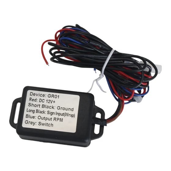
Model: GR01
1. Cable Definition
RED: Power Supply 12V DC
SHORT BLACK: Power GND
LONG BLACK : Input Signal Cable
BLUE: Output Signal (fixed 4pulses/round rpm ratio)
BROWN: Switch Control Cable
2. Configure Steps:
1) Connect Switch Cable to enter in setting mode
2) Find the Ignition Coil of your Gasoline Engine, normally it's close to Spark
Plug, which can be easily found from your engine/car/vehicle user guide.
Wrap the input signal cable 5~8 round across the ignition coil cable, and
then tighten like below:
Advertisement
Table of Contents

Subscribe to Our Youtube Channel
Related Manuals for Eling GR01


Summary of Contents for Eling GR01
- Page 1 Quick User Guide for Model: GR01 1. Cable Definition RED: Power Supply 12V DC SHORT BLACK: Power GND LONG BLACK : Input Signal Cable BLUE: Output Signal (fixed 4pulses/round rpm ratio) BROWN: Switch Control Cable 2. Configure Steps: 1) Connect Switch Cable to enter in setting mode 2) Find the Ignition Coil of your Gasoline Engine, normally it’s close to Spark...
- Page 2 3) Power on the Sensor, the LED will stay Green 4) Disconnect Switch Cable, the LED will still stay Green and calculate the detected pulse from engine 5) Connect Switch Brown Cable and Disconnect again, the LED will flash 6) The sensor output Pulse signal with fixed Tach RPM ratio 4pulese/round, which means it will output 66.6Hz when 1000RPM.
Need help?
Do you have a question about the GR01 and is the answer not in the manual?
Questions and answers