Advertisement
Quick Links
Advertisement

Related Manuals for Kodak alaris IMAGELINIK 3000DV Plus


Summary of Contents for Kodak alaris IMAGELINIK 3000DV Plus
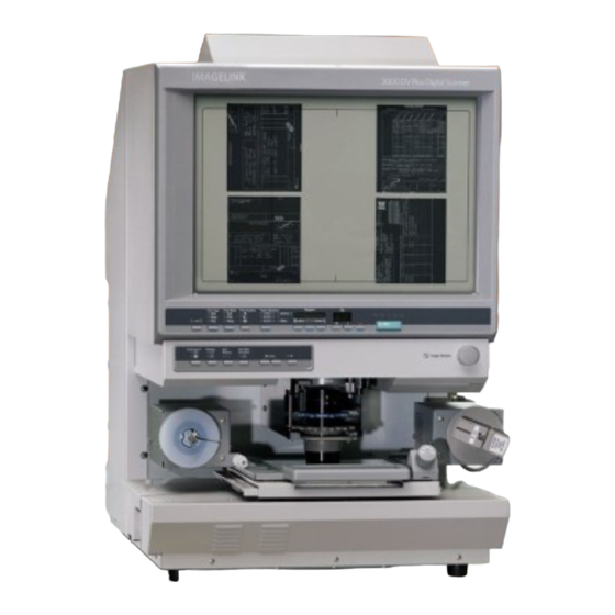
- Page 1 IMAGELINK 3000DV Plus and Accessories Installation Guide...
- Page 2 Unpacking Setting up...
- Page 3 Unpacking. 1. Remove the plastic bag from the machine. 2. Remove the various pieces of packing tape from the machine housing and the “cushion”. ...
- Page 4 4. Remove packing and pieces of tape holding each mirror. NOTE: If any pieces of tape are hard to peel off, remove the mirror assembly. ...
-
Page 5: Prism Assembly
Installing Prism Assembly. - Page 6 Installing the Prism Assembly. 1. Defeat the INTERLOCK SWITCH on the upper right of the screen (220/240VAC machines only). 2. Power up the machine. 3. Gently turn the IMAGE ROTATION KNOB clockwise or counterclockwise until the SHIELD PLATE is to the rear of the machine. ...
- Page 7 5. Swing down the SHIELD PLATE and install the PRISM as shown in the illustration. NOTE: Align SLIT A on the PRISM ASSEMBLY with cut out B in the SCANNING PLATE.
- Page 8 Checking the Screen Image. 1. Install the FILM CARRIER the customer will be using and power on the machine. 2. Install the Lens to be used in the machine. 3. With film not loaded, turn the ROTATION KNOB and check the screen image for a shadow from the SHIELD PLATE does not appear.
- Page 9 SHIELD PLATE Positioning adjustment. Follow this procedure if a shadow appears on the SCREEN while the IMAGE ROTATION KNOB is turned. 1. Turn the IMAGE ROTATION KNOB until the shadow from the SHIELD PLATE appears the largest on the bottom of the SCREEN. ...
- Page 10 3. Observe the following illustrations: If the position of the PRISM and SHIELD PLATE resemble illustration A: 1. Loosen the screws of the SHIELD PLATE and move it in the direction of the arrow. Tighten the Screws. ...
- Page 11 Connecting MSP3500 Printer.
- Page 12 Installing the Printer MSP3500. 1. Power down the Reader and the Printer. 2. Connect one end of the Printer cable supplied to the Interface Connector of the Reader. ...
-
Page 13: Personal Computer
Connecting to a Personal Computer. - Page 14 Connecting to a Personal Computer. The scanner is connected to a personal computer and the scanned images can be uploaded to the computer. ...
- Page 15 Installing Other Accessories.
- Page 16 Installing the Other Accessories. Mini Mars Controller option. 1. Install the two FERRITE CORES (grey in colour) supplied with the machine, to the INTERFACE CABLE between the Mars Controller and the Reader.
-
Page 17: Foot Switch
Foot Switch. Check all components in the FOOTSWITCH kit as complete before starting the installation. ... - Page 18 3. Install the STRAIN RELIEF from the kit as shown. 4. Connect the HARNESS plug to PJ10 on the PWB-BB PCB. NOTE. Route the HARNESS in the wire saddles as illustrated. ...
- Page 19 8. Install the two FERRITE CORES (white in colour) supplied with the machine as shown in the illustration. ...
- Page 20 Enabling the FOOTSWITCH 1. Apply power to the Reader and power on. 2. Enter Service Diagnostics by pressing the [CLEAR/STOP], [1] and [EXPOSURE MODE AUTO] keys for 2 seconds or more. The “Multi-Print” display will show “S” ...
- Page 21 17. Exit Service diagnostics by pressing [CLEAR/STOP], [1] and [EXPOSURE MODE AUTO] keys at the same time. NOTE: Update the Reader Configuration sheet stuck on the inside of the REAR COVER. 18. Check the Reader operation. ...
- Page 22 Universal Film Carrier. 1. Install the SHIELD MATERIAL supplied with the machine onto the rear side of the Universal Film Carrier as shown in the illustration. ...
- Page 23 Manual Frame Masking ...
- Page 24 Manual Frame Masking Kit Accessory. 1. Check the following components are in the Manual Masking Kit before starting the installation. NOTE: Before starting the installation check the Reader functions normally. 2. Power down the Reader and disconnect the power cord. ...
- Page 25 4. Disconnect the plug PJ2G of the harness that comes from the Control Panel PCB PWB-G2 on the machine. 5. Loosen the two screws on the rear side of the SCREEN FRAME and remove the POSITIONING PLATE from the bottom.
- Page 26 Install the MOUNTING BRACKETS removed in step 8 onto the new X-DIRECTION PANEL SWITCH ASSEMBLY using the original screws. 9. Install the X-DIRECTION PANEL on to the SCREEN FRAME using the original mounting screws.
- Page 27 12. Connect wiring HARNESS 1 from the Masking Kit to PXB-BB connector PJ-7. Route the HARNESS1 wiring loom along the top of the PWB-BB securing in the cable clamps. Feed the HARNESS 1 through the upper hole in the back side of the machine. ...
- Page 28 16. Connect the connectors from HARNESS 1 to the X-DIRECTION PCB on the back of the SCREEN FRAME. ...
-
Page 29: Screen Frame
21. Connect the 2P connector form the SCREEN FARME to the 2P connector of the machine. 22. Place wire harnesses on the left hand side of the machine in the wire saddles and secure the excess cables in the LARGE WIRE SADDLE fitted in step 15 with wire ties. - Page 30 Auto Focus Accessory ...
- Page 31 Installation instructions for the Auto Focus Accessory in the MS7000. Check the Auto Focus Kit contains all the following components before attempting to install the accessory. ...
- Page 32 NOTE: Before starting the installation check the Reader functions normally. 1. Power down the Reader and disconnect the power cord. 2. Loosen the screw in the top of the SCREEN FRAME and remove the SCREEN.
- Page 33 5. Remove the 7 screws and one SHOULDER SCREW which holds the LENS HOLDER COVER. IMPORTANT Do not remove any screws with RED PAINT on them. ...
- Page 34 7. Remove the PWB fixing screws on the back side of the LENS HOLDER COVER and install the REED SWITCH assembly contained in this kit. ...
- Page 35 10. Adjust the tension of the belt by moving the MOTOR ASSEMBLY in the direction of the arrow in the illustration. Tighten the mounting screws. NOTE The belt must be tight enough to transmit the drive ...
- Page 36 13. Feed the LEN COVER wiring harness into the reader screen area. Fit one of the CORD CLAMPS as shown in the illustration. ...
- Page 37 21. Secure the loose cabling in the wire saddles as shown in the illustration. NOTE Ensure no moving parts in the reader will touch the wiring harness by slowing moving the SCAN MIRROR ASSEMBLY. ...
- Page 38 26. Press the [DARKER] key to set the display to “o9” o -- o2….. --- o8 --- o9 NOTE The value decreases if the [LIGHTER] key is pressed. 27. Press the [EXPOSURE MODE AUTO] key. The current setting value of “d0”...
- Page 39 Installing AUTO FOCUS LENS Accessory Purpose: To install the AUTO FOCUS LENS accessory. Check the following items are in the kit before starting the installation. ...
- Page 40 2. Fix the magnets contained in the kit to the underside of the LENS GRIP ASSEMBLY according to the illustration below: ...
- Page 41 5. Insert the FIXED LENS into the LENS GRIP ASSEMBLY. NOTE The screw shown in the illustration will be installed later. Mount the LENS so the screw will enter the hole in the LENS. ...
- Page 42 8. Ensure the image is central on the Reader screen. Turn the ZOOM RING as necessary to find a reduction ratio of the film being used, see illustration. ...
- Page 43 11. Remove the LENS from the LENS GRIP ASSEMBLY. 12. Fit the STOPPER contained in the kit to the gear on the LENS GRIP ASSEMBLY.
- Page 44 14. Install the LENS ASSEMBLY into the Reader to check the Auto Focus is working correctly. Press the [AF] key, the Auto Focus should bring the screen image into focus. If not remove the LENS ASSEMBLY, remove the STOPPER installed in step 9 and start the procedure again beginning at step 1.
- Page 45 Greyscale Accessory. ...
- Page 46 Greyscale Accessory. Purpose: To install the GREYSCALE ACCESSORY option. 1. Power down the machine and remove the power cord. ...
- Page 47 3. Install the GREYSCALE ACCESSORY PCB on to the PWB-EE PCB. 4. Install the rear cover. 5. Check operation of the machine and the Greyscale Accessory. ...
Need help?
Do you have a question about the alaris IMAGELINIK 3000DV Plus and is the answer not in the manual?
Questions and answers