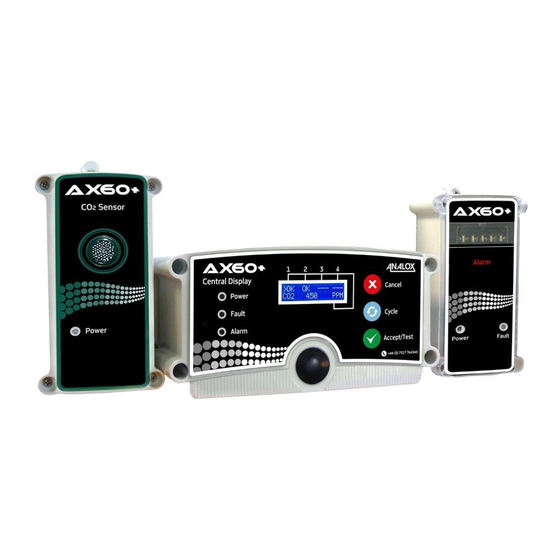
ANALOX AX60+ Quick Start Manual
Hide thumbs
Also See for AX60+:
- Service manual (62 pages) ,
- User manual (72 pages) ,
- Quick start manual (2 pages)
Advertisement
Quick Links
AX60+ Quick Connect Option
Quick Start Guide
Analox Sensor Technology Ltd
UK & RoW contact details:
15 Ellerbeck Court, Stokesley Business Park,
North Yorkshire, TS9 5PT, UK
Huntington Beach, California, 92649
T: +44 (0)1642 711400 F: +44 (0)1642 713900
T: (714) 891 4478 F: (714) 891 4479
W: www.analoxsensortechnology.com
W: www.analoxsensortechnology.com
E: info@analox.net
Copyright © 2018 Analox Ltd. All Rights Reserved.
Scan the QR code to
visit the Analox Ax60+
Web page
Introduction
This Quick Start Guide explains how to install the Ax60+ Quick Connect Option.
For more information on operation and maintenance, refer to the Ax60+ User
Manual P0159-800. This is available to download from www.analoxsensortechnol-
ogy.com. For more information on servicing and calibration, refer to the Ax60+
Service Manual P0159-803, this is also available to download from www.analoxsen-
sortechnology.com.
Step 1. Installing the Sensor and Alarm
CARBON DIOXIDE GAS (CO2) IS HEAVIER
THAN AIR AND SHOULD BE MONITORED
FROM A LOW HEIGHT. YOU SHOULD THERE-
FORE INSTALL A CO2 SENSOR AT A HEIGHT
OF 12–18" (305–457MM) ABOVE THE FLOOR
LEVEL.
OXYGEN (O2) SENSORS SHOULD BE IN-
STALLED AT AVERAGE WORKING HEAD
HEIGHT
Alarms should ideally be located at the entrances
to the danger area where visibility is not ob-
scured. Refer to your own risk assessment for
best location.
Retain the clear protective film on the fascia until
the installation is complete.
Using the supplied paper template mark out and
drill the wall-fixing position ensuring the unit is
level then install the wall plugs and fit the unit.
Step 2. Cabling
The supplied RJ45 coupler is used to connect two
US contact details:
RJ45 connectors.
15121 Graham Street #B106,
The RJ45 splitter is used to connect two Sensors or
two Alarms on a common cable.
E: ussales@analox.biz
•
White RJ45 connects Central Display-to-Sensor
and Sensor-to-Sensor.
•
Blue RJ45 connects Sensor-to-Alarm
Document ref: P0159-816-02
Step 3. Example of Optional Layouts
In its simplest form a Quick Connect Ax60+ system could incorporate a central
display, one sensor and one alarm. A larger Ax60+ system could incorporate a
central display, four sensors and eight alarms.
Step 4. Connecting the Sensor
Note: If the package has 2 sensors then
sensor 2 is identified by the number 2
label on top of the sensor enclosure.
The Sensor is pre-wired with:
•
A 5m cable with white RJ45 connector
for connection to the Central Display
•
A 5m cable with blue RJ45 connector
for connection to the Alarm(s)
Step 5. Connecting the Alarm
The Alarm is fitted with a 5-metre cable
with a blue RJ45 connector. This should
be connected to the blue connector of
the Sensor associated with the Alarm.
Step 6. PSU Cable Identification
PSU cables are connected to the Central Dis-
Plug-in type PSU cable identifi-
play via the terminal block labelled 'POWER'.
cation
Surplus cable can either be shortened or
Black with stripe: Positive (24V)
stored inside the Central Display enclosure.
Black with print: Negative (0V)
Step 7. Central Display Connections
The Central Display's terminal blocks must be connected to the power supply,
beacon and relays (the Sensor terminal block has a cable already fitted).
Advertisement

Subscribe to Our Youtube Channel
Related Manuals for ANALOX AX60+


Summary of Contents for ANALOX AX60+
- Page 1 Sensor associated with the Alarm. E: info@analox.net E: ussales@analox.biz • White RJ45 connects Central Display-to-Sensor Copyright © 2018 Analox Ltd. All Rights Reserved. and Sensor-to-Sensor. • Blue RJ45 connects Sensor-to-Alarm Scan the QR code to visit the Analox Ax60+...
- Page 2 Step 12. Securing the Power Supply Unit (PSU) Data Output Module If required secure the PSU in place using the securing kit supplied with the If a Data Output Module is required this is available for purchase from Analox. system. If relays are not required proceed to For set-up please refer to the quick start guide supplied with the module and also Step 11.
Need help?
Do you have a question about the AX60+ and is the answer not in the manual?
Questions and answers