
Related Manuals for Panasonic AW-PH650N


Summary of Contents for Panasonic AW-PH650N
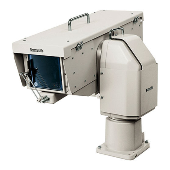
- Page 1 Outdoor Pan/Tilt Head AW-PH650N Before attempting to connect, operate or adjust this product, please read these instructions completely. Printed in Japan F0406Y1056 VQTB0104-1...
-
Page 2: Safety Precautions
Safety precautions CAUTION RISK OF ELECTRIC SHOCK DO NOT OPEN CAUTION: TO REDUCE THE RISK OF ELECTRIC SHOCK, DO NOT REMOVE COVER (OR BACK). NO USER SERVICEABLE PARTS INSIDE. REFER TO SERVICING TO QUALIFIED SERVICE PERSONNEL. The lightning flash with arrowhead symbol, within an equilateral triangle, is intended to alert the user to the presence of uninsulated “dangerous voltage”... -
Page 3: Important Safety Instructions
Safety precautions IMPORTANT SAFETY INSTRUCTIONS Read these operating instructions carefully before using the unit. Follow the safety instructions on the unit and the applicable safety instructions listed below. Keep these operating instructions handy for future reference. 1) Read these instructions. 2) Keep these instructions. -
Page 4: Table Of Contents
Contents Introduction ... 4 Accessories ... 4 Precautions for use ... 4 Installation precautions ... 5 Mounting (Pan/tilt head) ... 6 Precautions for installation ... 6 How to install ... 6 Mounting (AC adapter) ... 7 Precautions for installation ... 7 How to install ... -
Page 5: Installation Precautions
Installation precautions Do not install this unit by suspending it, and do not install it on its side. While factoring in the weights of the unit and the load that the unit will bear, select an installation location which is conducive to fastening the unit securely and which is level and without unevenness. -
Page 6: Mounting (Pan/Tilt Head)
Mounting (Pan/tilt head) Precautions for installation Do not install this unit by suspending it, and do not install it on its side. Using the four pan/tilt head mounting holes, fasten the unit securely with bolts which are long enough. The mounting holes have a diameter of 3/8”... -
Page 7: Mounting (Ac Adapter)
Mounting (AC adapter) Precautions for installation Be sure to use water-proof connecting cables. Be sure to keep AC power switched off during installation and connection. Before pressing the power switch on, make sure that all parts, including the housing and pan/tilt head, have been installed and connected completely and free of errors. - Page 8 Mounting (AC adapter) Connect the cables. (Refer to the “Connections”.) Make the distance between the AC adapter and pan/tilt head less than the length (30 m) of the power cable supplied. Pan/tilt head Ventilation opening AC power input Pole mounting plate...
-
Page 9: Parts And Their Functions
Parts and their functions Main unit (Pan/tilt head) Main unit cover The sunshade cover and main unit cover must be removed when the cable compensation circuit or landing characteristics are to be changed. Grip Used in carrying, installing, or lifting the pan/tilt head. -
Page 10: Housing Unit
Parts and their functions Housing unit Camera housing control board Connect the supplied camera cable. Air filter Air is taken in through the air filter. Replace it when it is clogged up. (Whenever the air filter needs replacement, ask the store where you purchased the product to do the job.) ... -
Page 11: Ac Adapter Unit
Parts and their functions AC adapter unit DC power unit This unit supplies a DC output of 15 V, 10 A (maximum) when an AC input of 120 V is supplied. Power switch [POWER ON/OFF] This switch is used to supply AC power to the DC power unit. -
Page 12: Supplied Cable Unit
Parts and their functions Supplied cable unit <Multi cable> (VEEB0133) 24P round water-proof plug (male) Connect this to the multi connector [MULTI] on the main unit. RJ-45 modular plug Connect this to pan/tilt head controller. It can be extended up to 3281 ft. (1000 m). To extend the connection, use a relay adapter purchased on the market and use a 10BASE-T straight cable (UTP category 5) for the extension. -
Page 13: Convertible Camera Cable (Veeb0176)
Parts and their functions <Power cable> (VEEB0152) 7P round water-proof plug (female) Connect this to the power connector [POWER] on the main unit. <Convertible camera cable> (VEEB0176) 26P connector (male) Connect this to the CAMERA I/F connector [CAMERA I/F] on the housing. -
Page 14: Installation
Installation Installing the housing mount frame Attach the housing mount frame (supplied) to the rotary arm of the main unit. Attach the housing mount frame to the rotary arm as shown in the figure below. The screws must be installed together with ... -
Page 15: Cable Compensation Circuit Settings
Installation Cable compensation circuit settings When the pan/tilt head and controller have been connected, the maximum allowable length of the connecting cables is 3281 ft. (1000 m) for the 10BASE-T straight cable (UTP category 5) and coaxial cable (BELDEN 8281). However, when using the cables beyond a distance of 1640 ft. -
Page 16: Cpu Circuit Board Switch Settings
Installation CPU circuit board switch settings Set switches SW1, SW2 and SW3 on the CPU circuit board as follows. SW1 (Selector switch for landing characteristics) For a soft landing: Set SW1 to the left position (RP501). (Factory setting) For an exact landing: Set SW1 to the right position (RP605). ... -
Page 17: How To Install The Camera
Installation How to install the camera Loosen the bolts for opening and closing the top cover, and open the top cover. Loosen the top cover open/close bolts The support arm completely enters the groove. Open the top cover until the support arm completely enters the groove. - Page 18 Installation <When the AW-E350 or AW-E650 camera is used> Use the 2 screws supplied with the camera to attach the mounting adapter (supplied with the camera) to the top panel of the camera. Attach the positioning screw (supplied) to the camera ...
- Page 19 Installation <When the AW-E655 camera is used> Attach the positioning screw (supplied) to the camera mounting spacer . Use the 2 screws (supplied) to attach the camera mounting spacer to the fan mounting seat on the top panel of the camera.
- Page 20 Installation <When the AK-HC1500 camera is used> Attach the positioning 1 screw (supplied) to the camera mount . Attach the camera mount using the 2 screws , flat washers and spring washers (supplied). (The camera mount points toward the front or back in the opposite way from a convertible camera.
- Page 21 Installation <When a regular lens is used> Sandwich the housing’s support rib between the camera mount and plate nut of the camera on which the camera mount has been installed, and provisionally secure it using the camera mount screws. Connect the camera with the lens to the interior of the ...
- Page 22 Installation <When a large lens is used> A large lens can be attached to the AK-HC910 or AK-HC1500, and stowed inside the housing for use. In a case like this, attach it by following the steps below. Use any of the large lenses listed below. HA42 ×...
- Page 23 Installation Check whether the “ ”-shaped part of the lens holder attached to the bottom of the lens is inside the elongated hole of the metal bracket inside the housing. If it is not inside, lift the lens slightly, and put it back again. Lens holder -shaped part of lens holder...
-
Page 24: How To Install The Housing
Installation How to install the housing Align the mounting rails () on the bottom of the housing with the housing mount frame () on the main unit, and fit the housing onto the side of the main unit. Move the housing to the rear, and push the I/F connector () on the housing in the direction of the arrow into the I/F connector () on the main unit. -
Page 25: Connections
Connections Concerning the connectors inside the housing The connectors shown in the figure below are provided inside the housing. Check the connection instructions for each of the cameras concerned, and connect them. LENS I/F (1) connector This is provided for controlling the zooming and focusing of the motorized lens unit. -
Page 26: Connecting The Cameras And Housing
Connections Connecting the cameras and housing 1. Connections with a convertible camera Use the supplied camera cable for these connections. Provide a coaxial cable [approx. 3.3 ft (1 m) long] (Size: 3C-FB or equivalent) Upon completion of the connections, bundle the routed cables together using the cable ties (supplied), making sure that the ... - Page 27 Connections 2. Connections with the AK-HC910 series In order to facilitate the connection procedure, stow the camera after connecting its I/F REMOTE connector. (Particularly when using a large lens, this connector must be connected before the camera is stowed.) Use the supplied camera cable for these connections. ...
- Page 28 Connections 3. Connections with the AK-HC1500 In order to facilitate the connection procedure, stow the camera after connecting its I/F REMOTE connector. (Particularly when using a large lens, this connector must be connected before the camera is stowed.) Use the supplied camera cable for these connections. ...
-
Page 29: Precautions When Controlling The Ak-Hc1500 From The Aw-Cb400
Connections Precautions when controlling the AK-HC1500 from the AW-CB400 The AK-HC1500 supports the AK-HRP150 protocol and AW-CB400 protocol, and it is the AK-HRP150 protocol which was set before the AK-HC1500 was shipped from the factory. When controlling the AK-HC1500 using the AW-CB400, follow the steps below to change the protocol setting of AK-HC1500 from AK-HRP150 to AW-CB400. -
Page 30: Example Of Connections When Using A Convertible Camera
Connections Example of connections when using a convertible camera Multi function controller AW-RP655 10BASE-T (UTP category 5) straight cable Cable compensation unit AW-RC400 10BASE-T (UTP category 5) straight cable The AW-RP555 can also be used as the controller. MULTI AC adapter AW-PS505A D-SUB 15pin RJ-45 relay adapter... -
Page 31: Example Of Connections When Using A Multi Purpose Camera
Connections Example of connections when using a multi purpose camera Camera controller AK-HRP150/AK-HRP900 Multi function controller AW-RP655 10BASE-T (UTP category 5) straight cable Precautions when using the AK-HC910 The AK-HC910 is capable of outputting HD-SDI signals and Y/PB/PR signals, but when the Y/PB/PR signals are used as the main line, do not connect any signals to the SDI IN/OUT connector. -
Page 32: Limiters
Limiters Be absolutely sure to set the limiters (travel range) of the pan/tilt head before use. Depending on where the pan/tilt head system has been installed, obstacles may be present within the travel range with which the camera may come into contact. Contact with any such obstacle by the camera may cause malfunctioning or accidents. -
Page 33: Releasing The Limiters
Limiters Releasing the limiters The set limits can be release by taking the following steps. • Releasing the upper limit of operating range 1. While holding down the OK button on the controller, press TRACING/PRESET MEMORY button 47 . 2. The release is completed when TRACING/PRESET MEMORY button 50 [LIMIT OFF] lights. -
Page 34: Replacement Of Consumable Parts
Replacement of consumable parts Replacing the battery The battery lasts for about 5 years. The pan/tilt head stores the preset positions, limiter positions and other data in its memory. Although this data is retained even after the power has been turned off, it will be lost when the power is turned off once the battery has reached the end of its service life. -
Page 35: Replacing The Motor
Replacement of consumable parts Replacing the motor Replace the motor when it ceases to operate properly. For details on the motor replacement, consult your dealer. Replacing the belt Replace the belt when the preset stop accuracy has deteriorated. For details on the belt replacement, consult your dealer. Replacing the gear Replace the gear when the preset stop accuracy has deteriorated. -
Page 36: Appearance
Appearance Main unit 8-3/8 (213) 6-11/16 (170) 9-5/16 (237) 7-1/2 (190) 6-5/16 (160) Unit: inch (mm) 3/16−ø3/8 (4−ø10) hole... -
Page 37: Housing Unit
Appearance Housing unit Unit: inch (mm) 9-11/16 (246) 27 (685) -
Page 38: Ac Adapter Unit
Appearance AC adapter unit 7-7/8 (200) 5-3/4 (146) 7/8 (22) 11 (280) 4-M8 nut 7-7/8 (200) Unit: inch (mm) -
Page 39: Cable Specifications
Cable specifications... - Page 40 Cable specifications...
- Page 41 Cable specifications...
-
Page 42: Specifications
Specifications Power supply: AC 120 V 60 Hz Power consumption: 120 W indicates safety information. General Ambient operating temperature –4°F to 113°F (–20°C to +45°C) Ambient operating humidity 30% to 90% (no condensation) Water-proofing standard supported IPX4 Weight Main unit: 41.9 lbs (19 kg) Housing unit: 39.7 lbs (18 kg) - Page 44 PANASONIC BROADCAST & TELEVISION SYSTEMS COMPANY UNIT COMPANY OF PANASONIC CORPORATION OF NORTH AMERICA Executive Office: One Panasonic Way 4E-7, Secaucus, NJ 07094 (201) 348-7000 EASTERN ZONE: One Panasonic Way 4E-7, Secaucus, NJ 07094 (201) 348-7621 Southeast Region: 1225 Northbrook Parkway, Ste 1-160, Suwanee, GA 30024 (770) 338-6835...
Need help?
Do you have a question about the AW-PH650N and is the answer not in the manual?
Questions and answers