Advertisement
Quick Links
Advertisement

Related Manuals for GANN HYDROMETTE HB 30


Summary of Contents for GANN HYDROMETTE HB 30
- Page 1 GANN HYDROMETTE HB 30 Operating Instructions...
- Page 2 Table of Contents Page Description of the measuring instrument ..............3 Measuring ranges ....................4 Battery, Dimensions and admissible ambient conditions ......... 5 - 6 Safety directions ....................7 - 8 Instructions for wood moisture measurement ............9 - 10 Use of measuring electrodes for wood moisture measurement ......
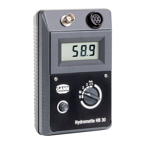
- Page 4 Technical Specifications - Hydromette HB 30 (1) BNC Connection Socket for connection of electrodes designed for testing wood and set building materials (2) 7-pin Connection Socket for connection of the active electrodes MB 35, B 50, B and IR 40...
- Page 5 Measuring ranges Wood Moisture, position »2-3«: 4 - 30 % m.c. Structural Moisture 1, position »B«: 0 - 80 digits with graphs for convert- readings into percent of moisture for various building materials Structural Moisture 2, position »M«: 0 - 199 digits non-destructive measurement with active electrode B 50 or B 60...
- Page 6 Temperature, position »M«: -20.0 - 200 °C with infrared sensor IR 40. If the measured value exceeds the measuring capacity, the figure »1« appears on the left side of the display screen (3). Battery Check Set selector switch (4) to position »Batt« and press measuring key (5). The reading displayed should be higher than 7.5 digits.
- Page 7 Dimensions Plastic casing: Length 140 mm x Width 90 mm x Height 42/50 mm. Weight: about 230 g without accessory. Admissible ambient temperatures Storage: 5 to 40 °C; temporarily -10 to 60 °C not condensing Operation: 0 to 50 °C, short term -10 to 60 °C not condensing The meter including accessory must not be stored or used in aggressive air or air contami- nated by solvents.
- Page 8 Important Safety Directions and General Remarks The following instructions should be carefully read and understood prior to first use of the moisture meter. No warranty claim can be accepted for any damage caused by non- observance of these instructions. The manufacturer can also not assume any responsibility for incidental or consequential damages.
- Page 9 ambient temperature dropping below dew point (formation of condensate). When using the measuring probes and connecting to or disconnecting them from the measur- ing instrument do not use force and do not pull on the cable. The measuring instrument, connecting cable and measuring probes must not be used or stored in aggressive or air containing solvents.
- Page 10 The measuring instrument and its standard and optional accessory must only be used as de- scribed in this manual. In view of the electromagnetic compatibility and the reliability of measurement, only the stan- dard and optional accessory described in this manual must be used with the measuring in- strument.
- Page 12 GANN meters are applied parallel to the grain. The effect can be neglected at readings below 10 % m.c., whereas around 20 % m.c. the meter will read about 2 % m.c. higher.
- Page 13 For stock with uniform moisture content, non-insulated pins can be used, whereas for all other applications insulated pins making contact only with their uncoated tip having a uniform contact area with the wood, regardless of the penetration depth, should be used. Any change in meter readings taken with insulated pins at different penetration depths clearly reflect an actual change in moisture content representing the existing moisture gradient.
- Page 14 Surface Electrodes M 20-OF 15 Surface measurements should only be taken when the wood moisture content is below 30 % m.c. For surface measurements on already machined stock, the two hexagon cap nuts have to be unscrewed and replaced with the surface measuring caps. For measurement, the two contact pads have to be pressed across the grain onto the stock to be measured.
- Page 15 When the M 18 electrode is supplied with the meter, 10 spare pins 40 mm and 60 mm long (without insulated shank) are included in the delivery. They are suitable for measuring wood up to 120 mm and 180 mm thick respectively. For testing timber with higher shell m.c. than core m.c., e.g.
- Page 16 Effects of Wood Preservers Treatment of wood with organic preservers or impregnating agents have, in general, little ef- fect on the meter readings. Treatment with preservatives containing salts or other inorganic constituents that change the conductivity of wood, however, has a great effect on the accu- racy of the readings and as it is erratic, a suitable table correction cannot be provided.
- Page 17 Static Electricity At wood moisture contents below 10 %, circumstances such as low air relative humidity, fric- tion during timber handling or highly insulated surroundings may cause static electricity of very high voltages. The operator too may contribute, e.g. by his clothing or shoes made of man-made fibre, to build up a static charge.
- Page 18 Once the wood has reached its moisture equilibrium, it will neither give off moisture nor ab- sorb it from the air, unless the ambient atmosphere changes. The following table shows some moisture equilibrium values which wood adopts at the various conditions specified. Wood Moisture Equilibrium Air Temperature in °C 10°...
- Page 19 16,2% 16,3% 16,0% 15,8% 15,6% 21,2% 21,2% 20,6% 20,3% 20,1% Operating instructions for moisture measurement of building materials according to the resistance method Set selector switch (4) to position »B«. Connect selected measuring electrode to the meter socket (1) by means of the measuring ca- ble MK 8 and press or stick electrode pins into the material to be measured.
- Page 20 On the meter side, this cable is fitted with a BNC plug. Turn clockwise to lock it. To discon- nect, turn notched fastening ring anti-clock- wise and draw off plug. Do not use force and do not pull on the cable. Testing Set Building Materials For testing soft building materials, the drive-in electrode M 20 should be used, whereas hard building materials such as concrete and cement flooring are to be measured with the stick-in...
- Page 21 impact resistant plastic). Take care that both pins of the electrode are driven only into the ma- terial to be tested. When withdrawing the electrode, the pins can be loosened by slight sideways rocking move- ments. The cap nuts should be tightened by means of a spanner prior to a series of measure- ments.
- Page 22 The two electrodes exclusively designed for moisture checks on set building materials are pressed, at approx. 10 cm apart, into the material to be tested. Both electrodes have to be in- serted into the same type of building material. Also, the section to be measured must be co- herent and not be crossed by any other material.
- Page 23 Deep Electrode M 21-100/250 These two electrodes, exclusively designed for the measurement of set building materials, al- low a measuring depth of up to 100 mm or 250 mm respectively. Insulated sleeves prevent the results from being distorted by a high degree of surface moisture such as dew or rain. Drill two 8 or 10 mm dia.
- Page 24 The contact paste is supplied in quantities of approx. 450 g in a plastic box sealed with a screw cap. It is used to produce a good contact between the electrode point and the building material to be measured or to serve as an extension to the electrode point. The moisture dis- placed by the drilling process is reconducted to the material to be measured by the water con- tained in the highly conductive contact paste.
- Page 25 Stick-in Electrodes M 6 - 150/250 The very thin electrode pins are specially designed for testing building or insulating materials for moisture content, if the pin holes shall be kept as small as possible. The two 2 mm dia. pins, made of ductile high-grade steel, can, for example, be sticked approx.
- Page 26 Set selector switch (4) to position »B« and press measuring key (5) when a reading of 45 dig- its should be obtained. A tolerance of ± 2 digits is admissible. Equilibrium Moisture Content What are generally referred to as equilibrium moisture value relates to an ambient temperature of 20 °C and an ambient air humidity of 65 % R.H.
- Page 27 room with an anhydrite subfloor, the PVC floor cannot be laid until the subfloor has dried to approx. 0.5 % m.c. On the other hand, parquetry flooring can be laid on a cement floor in a room with normal stove heating, with a moisture range of 2.5 to 3.0 % m.c. It is of prime importance to consider ambient conditions when determining the moisture con- tent of a building material.
- Page 29 Equilibrium Moisture Values in Per Cent of Dry Weight at 20 °C and at 20 °C and at 20 °C and 50 % R.H. 65 % R.H. 90 % R.H. Building Materials approx. approx. approx. Cement flooring (compressed, laid relatively dry) 1.7 –...
- Page 30 laid relatively wet) 2.4 – 2.6 Cement mortar 1 : 3 1.7 – 1.8 Lime mortar 1 : 3 1.8 – 1.9 Gypsum plaster, gypsum boards 0.6 – 0.7 Plaster flooring 0.8 – 0.9 Magnesite flooring 8.3 – 8.7 13.0 Stone-wood flooring acc.
- Page 31 Condition of material equalizing range moist White section: equilibrium moisture attained White-black section: equilibrating phase Caution: Floor covering or glues impervious to moisture should not yet been processed Black section: moist Performing any work should be avoided It should be noticed that a state of complete moisture equilibrium is usually achieved only after 1 -3 years.
- Page 39 Instructions For Non-Destructive Measurement of Structural Moisture Using the Active Electrodes MB 35, B 50 and B 60 Set selector switch (4) to position »M«. Connect electrode to meter socket (2) and apply it as described hereinafter. Press measuring key (5) and read result displayed by LCD readout (3). Active Electrode MB 35 The active electrode MB 35 has specially been developed for surface moisture measurement on concrete and sub-floorings and are suitable particularly for moisture checks prior to coating...
- Page 40 The readings displayed in per cent of dry weight can be converted into CM values according to the following table: % of dry weight 2.0 % CM Test Standard for Active Electrode MB 35 The optionally available test standard (Ref. No. 6073) permits the user to check the meter and the active electrode MB 35.
- Page 41 Active Electrodes B 50 and B 60 The active electrodes B 50 and B 60 are dielectric moisture sensors with integrated circuitry. They are intended specifically for determining moisture absorption and moisture distribution in building materials such as for example brickwork, concrete, screed, wood, insulating materi- als, etc.
- Page 42 Special feature of the active electrode B 60 The active electrode B 60 is equipped with a selector switch to set a limit value. It allows in conjunction with the also incorporated acoustic signal generator judgement of the tested building material without direct sight on the LCD readout. Whenever the reading exceeds the preset limit value, a whistle signal sounds.
- Page 43 Display Values (Digits) in Relation to the Material Bilk Density Density Corresponding Relative Air Humidity (specific wt. 30 - 50 70 80 90 95 100 of the build- ing material) Display in Digits kg / m³ very normal semi...
- Page 44 Display Values (Digits) in Percents of Weight Display (Digits) Cement % of dry mortar weight ditto % CM Anhydrite % of dry screed weight ditto % CM Concrete B % of dry 15, B 25, B 35 weight ditto % CM Cement % of dry mortar...
- Page 45 The values in per cent of dry weight or in CM-% stated in the table overleaf are guide values. They refer to a normal drying progress and the usual moisture gradient between surface and the possible measuring depth which depends on the density of the material tested. If the building material dries too fast, e.g.
- Page 46 Instructions for Temperature Measurement with Active Electrode IR 40 Set selector switch (4) to position »M«. Connect temperature probe to meter socket (2). Adjust temperature probe to the desired measuring spot and press measuring key (5). Read off result in °C. Technical Specifications Measuring range: -20 °C to +199.9 °C.
- Page 47 Operation: 0 °C to 50 °C; 90 % R.H. maximum, not condensing. General Information Concerning Infra-Red Temperature Measurement Technique All bodies with a temperature above the »absolute zero« (= 0 °K or -273 °C) emit infra-red radiation, also known as thermal radiation. The intensity of this thermal radiation serves as an indication of the surface temperature, having regard to the degree of emission.
- Page 48 Measure Turn selector switch (4) to position »M«. Insert the plug of the connection cable into the socket (2) and engage by gently turning clockwise. Follow the reverse procedure to remove the plug. Do not apply force and do not stretch the cable. Immediately after pressing the measuring key, the reading is displayed in °C.
- Page 49 In order to avoid measurement errors and to protect the equipment against damage, the user should not ● press the sensor opening of the measurement sensor directly against the object being measured, ● measure in an atmosphere that is contaminated or contains vapour, ●...
- Page 50 The measurement sensor is set to a degree of emission of 95 %. This value covers most building materials, synthetic materials, textiles, paper and non-metallic surfaces. The following list is used to estimate the emission factor, which is affected by, among other things, the shine and roughness of the object being measured.
- Page 51 Brickwork (rough) 90 to 95 % Plaster 90 to 95 % Cement 90 to 95 % Plastic materials 90 % Ceramics 90 to 95 % Roofing fabric 95 % Clay 95 % Sand 90 % Concrete 95 % Textiles * 95 % Earth 95 %...
- Page 53 Measuring electrodes and other accessory Drive-in Electrode M 20 (Ref. No. 3300) for surface and subsurface measurements on wood up to 50 mm thick. Also for testing chipboard, fibreboard and set construction materials (plaster, mortar, etc.), with measuring pins - 16 mm long (Ref. No. 4610), penetration depth 10 mm - 23 mm long (Ref.
- Page 54 Ram-in Electrode M 18 (Ref. No. 3500) for testing timber up to 180 mm thick, with uninsulated pins, as standard equipment, - 40 mm long (Ref. No. 4640), penetration depth 34 mm - 60 mm long (Ref. No. 4660), penetration depth 54 mm, or optionally with pins with insulated shank - 45 mm long (Ref.
- Page 55 Brush Electrodes M 25 (Ref. No. 3740) made of stainless steel, for moisture measurements of hard and soft building materials without contact paste, measuring depth up to 100 mm. Stick-in Electrodes M 6 (Ref. No. 3700) for testing hard building materials, using contact paste and pre-drilled holes, with pins - 23 mm long (Ref.
- Page 56 Flat Electrodes M6-Bi 200/300 for measurements in insulating material of cement flooring through the edge joint (with insulated shank), only for use in conjunction with the handles of the electrodes M 6. - size 10 x 0.8 x 200 mm (Ref. No. 3702) - size 10 x 0.8 x 300 mm (Ref.
- Page 57 Deep Electrodes M 21-100/250 for deep measurements in set building materials, in conjunction with contact paste and pre-drilled holes - 100 mm long (Ref. No. 3200) - 250 mm long (Ref. No. 3250). Contact Paste (Ref. No. 5400) to ensure good contact between electrode pins and tested building materials.
- Page 58 Active Electrode B 50 (Ref. No. 3750) with integrated measuring circuit, designed for non- destructive location of moisture concentration in con- struction materials and moisture distribution in walls, ceilings and floors. It works according to a special measuring procedure and generates a concentrated high frequency field with substantial penetration depth.
- Page 59 Active electrode B 60 (Ref. No. 3760) with integrated measuring circuit, designed for non. destructive location of moisture concentration in con- struction materials and moisture distribution in walls, ceilings and floors. It work according to a special measuring procedure and generates a concentrated high frequency field with substantial penetration depth.
- Page 60 Infrared Surface Temperature Sensor IR 40 (Ref. No. 3150) Contactless temperature measurement from -20 to +199.9 °C, resolution 0.1 °C, emissivity permanently set at 95 %, ratio of measured area to distance 2.5:1 (Ø 45 mm at a distance of 100 mm), sensor length 185 mm x 36 x 33 mm, coiled cable 320/ 1200 mm.
- Page 61 Carrying Case (Ref. No. 5085) for storing and transport of the measuring instrument and the standard and optional accessory Measuring Cable MK 8 (Ref. No. 6210) for connection of the electrodes M 6, M 18, M 20, M 20-HW and M 21 Rechargeable Battery with Charging Unit (Ref.
- Page 62 Test Devices Test Standard (Ref. no. 6070) for checking the wood moisture measuring section of the measuring instrument. Test Standard (Ref. No. 6071) for checking the measuring section for building materials. Test Standard (Ref. No. 6073) for checking the active electrode MB 35.
- Page 63 Warranty GANN warrants for six months from date of purchase or one year from date of delivery from his factory whichever period elapses first, to correct by repair or replacement of defective parts free of charge any product defect due to faulty material or poor workmanship. Replace- ment or repair of any part do not constitute a new warranty period or an extension of the original warranty period.
- Page 64 EC Directive on Electromagnetic Compatibility 89/336/EEC in version 93/31/EEC We hereby declare that the handheld moisture meter GANN HYDROMETTE HB 30 corresponds to the aforementioned directive both with respect to its conception and type of construction and the design as marketed by us.
- Page 65 GANN Mess- u. Regeltechnik GmbH, Stuttgart, Germany...
Need help?
Do you have a question about the HYDROMETTE HB 30 and is the answer not in the manual?
Questions and answers