Advertisement
Quick Links
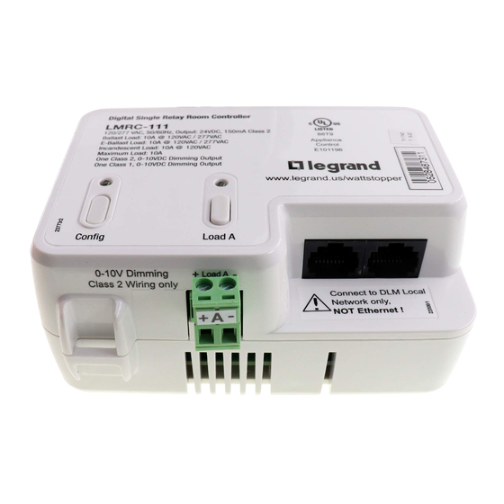
THIS UNIT IS SET FOR
PLUG N' GO™ OPERATION, ADJUSTMENT
IS OPTIONAL.
For full operational details see the DLM Dimming
System Installation Guide provided with the room
controller and also available at
www.wattstopper.com
Installation shall be in accordance with all
applicable regulations, local and NEC codes.
Wire connections shall be rated suitable for the wire
size (lead and building wiring) employed.
WARNING: TO CONNECT A COMPUTER TO THE
DLM LOCAL NETWORK USE THE LMCI‑100.
NEVER CONNECT THE DLM LOCAL NETWORK
TO AN ETHERNET PORT – IT MAY DAMAGE
COMPUTERS AND OTHER CONNECTED EQUIPMENT.
PLACEMENT EXAMPLE
Corner Mount
Occupancy
Sensor
LMRC-11x
Room Controller
J Box
Daylighting
Sensor
To
Load
Class 2 to 0-10V
Dimming Ballast
CAUTION: TURN THE
POWER OFF AT THE CIRCUIT
BREAKER BEFORE WIRING.
MOUNTING, WIRING, AND CONNECTING TO A DLM NETWORK
The LMRC-111/112 room controller can be mounted external to any junction box with 1/2" knockouts, placing it in the plenum space.
All line voltage wiring is #16 AWG. Each relay is rated for up to 10A; total load for LMRC-112 not to exceed 10A. Specified load types can
connect to any load relay. Do not connect different load types to the same relay.
For dimming ballasts, either or both the Class 1 and Class 2 0-10V wires may be connected. For Class 1 Dimming, wiring is 18# AWG.
Connect the 0-10V control wires to the 0-10V terminals that match the load relay output connection.
Class 1 is preferred in new installations when the violet and grey dimming signal wires are included in the fixture power cable. Class 2 is
used for new or existing installation when it is easier to run the violet and grey dimming signal wires outside the fixture cable.
Class 1 and Class 2 wiring should be maintained thoughout the installation and cannot be swapped - appropriate wiring practices should
be used. Class 1 and Class 2 circuitry in the LMRC units are galvanically isolated.
The LMRC-111/112 communicates to all other DLM devices connected to the DLM Local Network. Connections shown are for example
only. The low voltage LMRJ cables can connect to any DLM device with an open RJ45 receptacle.
Single/Dual Relay w/0-10V Dimming Room Controller
DLM Local Network
(low voltage, Class 2)
LMRJ cables
Ceiling Mount
Occupancy
Sensor
Switch/
Dimmer
LMRC-111/112
Digital Lighting Management (DLM)
LMRC-111 / LMRC-111-M
SPECIFICATIONS
Input Voltage ..................................................... 120/277VAC, 50/60Hz
Load Requirements........................................ Not to exceed 10A total
Relay rated for up to:
Incandescent ...................................................... 10A @ 120VAC
Ballast .........................................................10A @ 120/277VAC
E-ballast ......................................................10A @ 120/277VAC
Output to DLM Local Network ......................... up to 150mA @ 24VDC
Class 1 & 2 Dimming Output, 0-10V sinks up to 50mA per channel
DLM Local Network Characteristics when using LMRC-111/112:
Provides low voltage power over Cat 5e cable (LMRJ); max current
800mA. Supports up to 64 load addresses, 48 communicating
devices including up to 4 LMRC-10x series and/or LMPL-101
controllers. Free topology up to 1,000' max.
Metering capability in LMRC-111-M and LMRC-112-M provides power
monitoring within 2% of the true value.
Power monitoring capability when used with LMSM Segment Manager.
Environment:
Operating Temperature ....................32° to 131°F (0° to 55°C)
Storage Temperature ...................... 23° to 176°F (-5° to 80°C)
Relative Humidity ........................... 5 to 95% (non condensing)
UL 2043 Plenum Rated, ROHS Compliant
LMRC-112 / LMRC-112-M
Advertisement

Related Manuals for wattstopper LMRC-111


Summary of Contents for wattstopper LMRC-111
- Page 1 MOUNTING, WIRING, AND CONNECTING TO A DLM NETWORK The LMRC-111/112 room controller can be mounted external to any junction box with 1/2” knockouts, placing it in the plenum space. All line voltage wiring is #16 AWG. Each relay is rated for up to 10A; total load for LMRC-112 not to exceed 10A. Specified load types can connect to any load relay.
- Page 2 Press & release for See DLM device Quick Start Guides to determine how each ON/OFF. device affects the PNG operation of the LMRC-111/112. Press & hold to Dim. Load Control Arbitration To take full advantage of automatic PnG configuration, review...
- Page 3 ON. The red LED on the LMRC-111/112 begins to blink. When you release the button, the red LEDs on other • To unbind an occupancy sensor, press the up () or down Config button &...
- Page 4 WARRANTY INFORMATION WattStopper warranties its products to be free of defects in materials and workmanship for a period of five (5) years. There are no obligations or liabilities on the part of WattStopper for consequential damages arising out of, or in connection with, the use or performance of this product or other indirect damages with respect to loss of property, revenue or profit, or cost of removal, installation or reinstallation.