Advertisement
THIS UNIT IS SET FOR
PLUG n' GO
™
OPERATION,
ADJUSTMENT IS
OPTIONAL.
For full operational details
see the DLM Dimming
System Installation
Guide provided with the
room controller and also
available at
www.wattstopper.com
FOR CONNECTION TO
PLUG LOADS ONLY.
INSTALLATION SHALL BE
IN ACCORDANCE WITH ALL
APPLICABLE REGULATIONS,
LOCAL AND NEC CODES.
Wire connections shall be rated
suitable for the wire size (lead
and building wiring) employed .
PLACEMENT EXAMPLES
Line Voltage
(Class 1 wiring)
To Plug Load
(Class 1 wiring)
To Other
Electrical
Outlets
CONNECTIVITY
The LMPL-201 communicates to all other
DLM devices connected to the DLM Local
Network . Connections shown are for
example only . The low voltage LMRJ cables
can connect to any DLM device with an open
RJ45 receptacle .
All line voltage wiring is #12 AWG .
WARNING:
TO CONNECT A COMPUTER TO THE
DLM LOCAL NETWORK USE THE
LMCI‑100. NEVER CONNECT THE DLM
LOCAL NETWORK TO AN ETHERNET
PORT – IT MAY DAMAGE COMPUTERS
AND OTHER CONNECTED EQUIPMENT.
MOUNTING THE
CONTROLLER
The plug load room
controller mounts as the
cover for a four square deep
junction box . It is equipped
with a lash and hook to hang
the controller from a j-box
cover tab while connecting the line voltage
wires . After securely connecting the wires,
unhook the lash from the j-box and secure
the controller to the j-box cover tabs using
two screws .
xxxxxr1
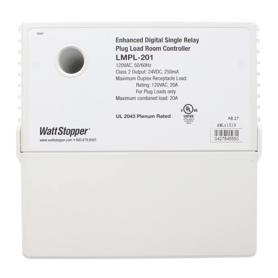
Enhanced Digital Single Relay
Plug Load Room Controller
LMPL-201
120VAC, 50/60Hz
Class 2 Output: 24VDC, 250mA
Maximum Duplex Receptacle Load:
Rating: 120VAC, 20A
For Plug Loads only
Maximum combined load: 20A
UL 2043 Plenum Rated
www.wattstopper.com • 800.879.8585
Patent Pending
For Class 2 DLM devices and device wiring:
To be connected to a Class 2 power
source only .
Do not reclassify and install as Class 1,
or Power and Lighting Wiring .
WARNING: Do not install to cover a
junction box having Class 1, 3 or Power
and Lighting Circuits .
J-Box
Plug Load
Controller
Ceiling Mount
Occupancy
Sensor
Corner Mount
Sensor
Switch
4-square
deep
J-box
Hook
Lash
Hook
Lash
Use a 4"x 4"x 2
1
/
8
deep (minimum) box
APPLIANCE
CONTROL
88T9
Input Voltage: . . . . . . . . . . . . . . . . . . . . . . . . . . . . . . . 120VAC, 50/60Hz
Load Rating:
Maximum Duplex Receptacle Rating . . . . . . . . . . . . . 120VAC, 20A
Class 2 Output to DLM Local Network . . . . . . up to 250mA @ 24VDC
DLM Local Network Characteristics when using LMPL-201:
Provides low voltage power over Cat 5e cable (LMRJ);
max current 800mA . Supports up to 64 load addresses, 48
communicating devices including up to 4 LMRC-10x series and/
or LMPL-101 and/or LMPL-201 controllers . Free topology up to
1,000' max .
Environment:
Operating Temperature . . . . . . . . . . . . . .32° to 158°F (0° to 70°C)
Storage Temperature . . . . . . . . . . . . . . 23° to 176°F (-5° to 80°C)
Relative Humidity . . . . . . . . . . . . . . . . . 5 to 95% (non condensing)
Line Voltage
(Class 1 wiring)
Line Voltage
(Class 1 wiring)
To Plug Load
(Class 1 wiring)
Switch
To Other
Electrical
Outlets
Ceiling Mount
DLM Local Network
Sensor
Low Voltage
LMRJ Cables
Dimmer
LMPL or
LMRC series
Room Controller
ATTACHING LMRJ LOW VOLTAGE CABLES
Remove rubber jack covers to use RJ45 receptacles .
Leave covers in place for all unused receptacles .
LMPL-201
Digital Lighting Management (DLM)
Enhanced Digital Single Relay
Plug Load Room Controller
CAUTION:
TURN THE
POWER OFF AT THE CIRCUIT
BREAKER BEFORE WIRING.
Room
Controller
J-Box
J-Box
Plug Load
To Lighting
Controller
Load
(Class 1 wiring)
Ceiling Mount
Occupancy
Sensor
Line
Earth Ground/Green wire
Voltage
Line/Hot
Black wire
Plug Load
Controller
Neutral
White wire
Red wire to Switched Receptacle
Deep J-Box
Black wire w/white stripe to Unswitched Receptacle
Switch
Loads
Ground
Switched
Receptacle
Unswitched
Ground
Receptacle
Advertisement
Table of Contents

Related Manuals for wattstopper LMPL-201


Summary of Contents for wattstopper LMPL-201
- Page 1 800mA . Supports up to 64 load addresses, 48 communicating devices including up to 4 LMRC-10x series and/ FOR CONNECTION TO Patent Pending or LMPL-101 and/or LMPL-201 controllers . Free topology up to PLUG LOADS ONLY. 1,000’ max . For Class 2 DLM devices and device wiring:...
- Page 2 PLUG n’ GO OPERATION (PnG) Load A ON/OFF button The plug load circuit connected to the LMPL-201 is automatically controlled by all occupancy sensors on the Blue LED ON when switched DLM local network . After the last occupancy sensor’s receptacle circuit is ON .
Need help?
Do you have a question about the LMPL-201 and is the answer not in the manual?
Questions and answers