Table of Contents
Advertisement
Quick Links
THIS UNIT IS PRE-SET FOR PLUG n' GO™
OPERATION, ADJUSTMENT IS OPTIONAL.
For full operational details, adjustment and more
features of the product, see the DLM System Installation
Guide provided with the LMRC-102 room controller,
www.wattstopper.com
and also available at
INSTALLATION SHALL BE IN ACCORDANCE WITH ALL
APPLICABLE REGULATIONS, LOCAL AND NEC CODES.
Wire connections shall be rated suitable for the wire
size (lead and building wiring) employed .
For Class 2 DLM devices and device wiring:
To be connected to a Class 2 power source only .
Do not reclassify and install as Class 1, or Power and Lighting Wiring .
WARNING: Do not install to cover a junction box having Class 1, 3 or
Power and Lighting Circuits .
PLACEMENT EXAMPLE
Daylighting
Sensor
MOUNTING THE CONTROLLER
The LMRC‑102 room controller can either be mounted
external to a junction box, placing it in the plenum space or
mounted directly inside a 4" x 4" junction box .
J-Box
Outside a 4" x 4" box
CONNECTIVITY
The LMRC‑102 communicates to all other DLM
devices connected to the DLM Local Network .
Connection drawings are for example only . The
low voltage LMRJ cables can connect to any DLM
device with an open RJ45 receptacle .
All line voltage wiring is #12 AWG . Each relay is
rated for up to 20A, total load for LMRC‑102 not
to exceed 20A .
DLM Local Network
(low voltage, Class 2)
Corner Mount
Occupancy
Sensor
Room
Controller
J Box
To
Load
Ceiling Mount
Occupancy
Sensor
J-Box
Inside a 4" x 4" box
Corner Mount
Sensor
Switch
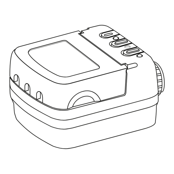
LMRC-102
Digital Lighting Management (DLM)
Dual Relay Room Controller
Input Voltage . . . . . . . . . . . . . . . . . . . . . . . .120/230/277VAC, 50/60Hz
Load Requirements . . . . . . . . . . . . . . . . . . . . .Not to exceed 20A total
Each relay rated for up to:
Incandescent . . . . . . . . . . . . . . . . . . . . . . . . . . 20A @ 120VAC
Ballast . . . . . . . . . . . . . . . . . . . . . . . . . . . .20A @ 120/277VAC
Motor . . . . . . . . . . . . . . . . . . . . . . . . . . . . 1Hp @ 120/240VAC
Output
. . . . . . . . . . . . . . . . . . . . . . . . . . . . . . . . . . . .150mA @ 24VDC
DLM Local Network Characteristics:
Provides low voltage power over Cat 5e cable (LMRJ) .
Supports up to 24 communicating devices, including 4
LMRC‑10x or LMPL‑101 max per each DLM Local Network .
Free topology up to 1,000ft of low voltage cable .
Environment:
Operating Temperature . . . . . . . . . . . . . .32° to 104°F (0° to 40°C)
Storage Temperature . . . . . . . . . . . . . . 23° to 176°F (‑5° to 80°C)
Relative Humidity . . . . . . . . . . . . . . . . . 5 to 95% (non condensing)
Patent Pending
LMRJ cables
POWER OFF AT THE CIRCUIT
BREAKER BEFORE WIRING.
WARNING:
LMCI-100. NEVER CONNECT THE DLM
Switch
AND OTHER CONNECTED EQUIPMENT.
ATTACHING CABLES
Remove rubber jack covers if using all 3 RJ45 receptacles .
Leave covers in place for all unused receptacles .
Ceiling Mount
Sensor
DLM Local Network
Low Voltage
LMRJ Cables
Controller
Switch
Daylight Sensor
CAUTION:
TURN THE
TO CONNECT A COMPUTER TO THE
DLM LOCAL NETWORK USE THE
LOCAL NETWORK TO AN ETHERNET
PORT – IT MAY DAMAGE COMPUTERS
Line
Voltage
Line/Hot
Neutral
Black wire
White wire
LMRC
102
Room
Yellow wire
Red wire
to Load 2
to Load 1
J-Box
Loads
1
2
Advertisement
Table of Contents

Subscribe to Our Youtube Channel
Related Manuals for wattstopper legrand LMRC-102


Summary of Contents for wattstopper legrand LMRC-102
- Page 1 Incandescent . . . . . . . . . . . . . . . . . . . . . . . . . . 20A @ 120VAC www.wattstopper.com and also available at Ballast .
- Page 2 1 . Make sure the DLM local network is not in PnL . load doesn’t switch 2 . Check load connections to room controllers and/or plug load controllers . Please 6/19/2009 2800 De La Cruz Blvd . Phone: 800 .879 .8585 Recycle Santa Clara, CA 95050 www .wattstopper .com 11589...
Need help?
Do you have a question about the legrand LMRC-102 and is the answer not in the manual?
Questions and answers