Advertisement
Quick Links
SPECIFICATIONS
Input voltage ..................................................115/277V 60 Hz
Class 2 connection to two independent DLM local networks (IRB)
24VDC output, up to 250mA across 2 RJ45 ports per
local network (A and B networks, 250 mA each)
If using an optional LMRC-100 to boost output, the
amount is 400 mA per network (two LMRC-100s
needed if using both networks)
Free-topology DLM local network segments may include
LMFC-011 Fixture Controllers, DLM switches, occupancy
sensors, daylight sensors and input modules
Category 5e cable, up to 1,000 ft. total per local network
Terminals for connection to DLM segment network
(BACnet MS/TP)
Segment network parameters
WattStopper LM-MSTP wire
Linear topology; 4000 ft. maximum per segment
Operating conditions:
for indoor use only ...................... 32-122 F (0 – 50 C)
........................................ 5-95% RH, non-condensing
UL and cUL listed
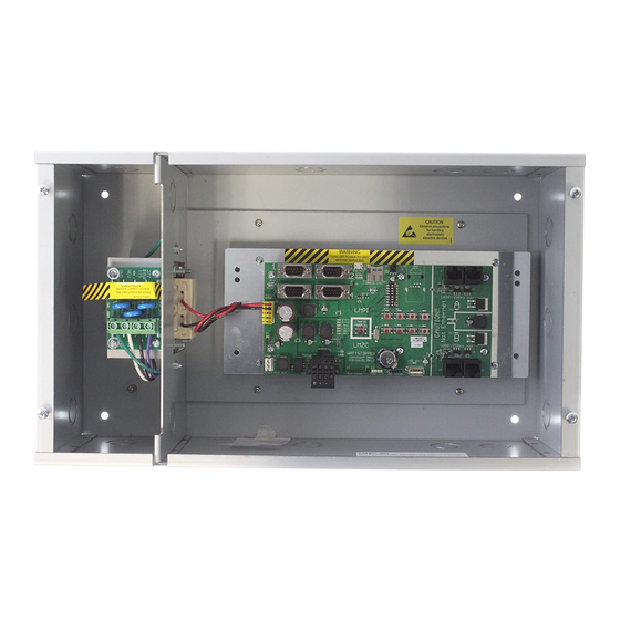
Step 2
Mount the LMCZ-301, using 4 mounting screws.
Step 4
Connect the incoming power cable to the power supply (and if used,
to the LMRC-100).
Connect as shown below for 115V
Green
(Ground)
White
(Neutral)
Connect as shown below for 277V
Green
Black
(Ground)
(Line)
White
(Neutral)
Step 1
Remove the P115/277 board with the LMPI assembly
Step 3
Reinstall the P115/277 board with the LMPI assembly
Note: If installing an optional LMRC-100s, attach it to the
power supply board before reinstalling. See the instructions
at the bottom of the following page.
Black
(Line)
Wiring for an LMRC-100
Green
(Ground)
White
(Neutral)
Black
(Line)
LMZC-301
DLM Zone Controller
Wiring for two LMRC-100s
Green
(Ground)
White
(Neutral)
Black
(Line)
Advertisement

Related Manuals for wattstopper LMZC-301


Summary of Contents for wattstopper LMZC-301
- Page 1 Category 5e cable, up to 1,000 ft. total per local network Terminals for connection to DLM segment network (BACnet MS/TP) Segment network parameters WattStopper LM-MSTP wire Linear topology; 4000 ft. maximum per segment Operating conditions: for indoor use only ...... 32-122 F (0 – 50 C) ........
- Page 2 WARRANTY INFORMATION WattStopper warranties its products to be free of defects in materials and workmanship for a period of five (5) years. There are no obligations or liabilities on the part of WattStopper for consequential damages arising out of, or in connection with, the use or performance of this product or other indirect damages with respect to loss of property, revenue or profit, or cost of removal, installation or reinstallation.
Need help?
Do you have a question about the LMZC-301 and is the answer not in the manual?
Questions and answers