Table of Contents
Advertisement
Quick Links
Advertisement
Table of Contents

Related Manuals for Mikster INDU-52


Summary of Contents for Mikster INDU-52
- Page 1 Industrial Microprocessor Controller INDU-52 Intended for; heat boilers, smoke houses, industrial ovens, Sp. z o.o. 41-250 Czeladź ul. Wojkowicka 21 POLAND Tel. +48 32 763 –77– 77, Fax: +48 32 763 –75 –94 www.mikster.com mikster@mikster.com v 1.1 17.01.2006...
-
Page 2: Table Of Contents
User’s Manual for ‘INDU-52’ v1.1 Table of Contents Application ....................3 Technical Specifications ................3 Controller Operating Modes................. 4 Process Parameter Changing..............4 Process Start ....................5 Process Stop ....................5 Continuous Control Mode ................5 Info....................... 5 Setup ......................6 Alarms ...................... -
Page 3: Application
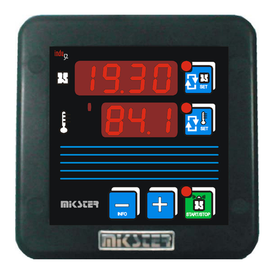
– temperature temperature setpoint setpoint editing START/STOP Fig: 1 INDU-52 Controller Front Panel 2. Technical Specifications Display LED ½ ’’ x 4 digits LED ½ ’’ x 3 digits 230 (option 110, 24) VAC ± 10% Power Supply Keyboard... -
Page 4: Controller Operating Modes
User’s Manual for ‘INDU-52’ v1.1 3. Controller Operating Modes The controller can run in the following modes: START: in this mode the process control is carried out according to the measured temperate and the preset START mode time is counted down. Output 1 (Re1) is controlled according to measurements made in Channel 1 (Ch1). -
Page 5: Process Start
User’s Manual for ‘INDU-52’ v1.1 5. Process Start Press the START key to run the process. When the START mode is activated the START key flashes. The time to the process end is shown on the upper display. The end of the process is indicated by “STOP” appearing on the display and by an audible signal. -
Page 6: Setup
User’s Manual for ‘INDU-52’ v1.1 9. Setup To get into the Setup menu press and hold down the MINUS key and then press the START key. Enter the access code with the PLUS / MINUS keys and confirm it by pressing any SET key, if the access code function is enabled. -
Page 7: Alarms
User’s Manual for ‘INDU-52’ v1.1 Alarms After power supply is switched on the measuring elements are tested by the controller. Should a faulty measuring element is found the upper display shows “Err” and corresponding channel number. Such information shall be confirmed by pressing the INFO key. -
Page 8: Notes
User’s Manual for ‘INDU-52’ v1.1 Notes 17.01.2006... - Page 9 User’s Manual for ‘INDU-52’ v1.1 Notes 17.01.2006...
Need help?
Do you have a question about the INDU-52 and is the answer not in the manual?
Questions and answers
Guten Tag, beim Gerät Mikster (Indu 52) ist heute beim Temperatur einstellen, die Meldung im Display siehe Foto gekommen. Es sind 3 waagrechte Striche. Ein Elektriker hat heute kurz in die Steuerung geschaut und meint, das der Fühler defekt ist, da das Relais **** mehr schaltet. Mein Chef Hr. Grober hat heute bei Ihnen einen neuen Kessel bestellt, daher die Frage, ob Sie wissen, was der Fehler sein kann, und das defekte Teil evtl. zusenden können. Oder ist es besser, wenn ein Techniker von Ihnen vorbei kommt. Danke Alain Ullmann Snack Attack GmbH
The error message with three horizontal lines (“---”) on the Mikster INDU-52 indicates that the measuring range has been exceeded or the measuring element is damaged. The manual does not specify whether a replacement part can be provided.
This answer is automatically generated