Table of Contents
Advertisement
Available languages
Available languages
Quick Links
mikster.eu
INDU-50
Instrukcja obsługi v1.91(85)
INDUSTRIAL MICROPROCESSOR
CONTROLLER INDU-50
User's Manual v. 1.8
MIKROPROCESOROVÁ ŘÍDICÍ
JEDNOTKA INDU-50
Uživatelský manuál v. 1.8
ПРОМЫШЛЕННЫЙ
МИКРОПРОЦЕССОРНЫЙ
КОНТРОЛЛЕР INDU-50
Руководство
пользователя v. 1.8
DES MIKROPROZESSORSTEUERGERÄTES
INDU-50
BEDIENUNGSANLEITUNG v. 1.8
Advertisement
Chapters
Table of Contents

Related Manuals for Mikster INDU-50


Summary of Contents for Mikster INDU-50
- Page 1 INDU-50 Instrukcja obsługi v1.91(85) INDUSTRIAL MICROPROCESSOR CONTROLLER INDU-50 User’s Manual v. 1.8 MIKROPROCESOROVÁ ŘÍDICÍ JEDNOTKA INDU-50 Uživatelský manuál v. 1.8 ПРОМЫШЛЕННЫЙ МИКРОПРОЦЕССОРНЫЙ КОНТРОЛЛЕР INDU-50 Руководство пользователя v. 1.8 DES MIKROPROZESSORSTEUERGERÄTES INDU-50 BEDIENUNGSANLEITUNG v. 1.8...
- Page 2 Polski 4-32 English 33-62 Český Pусский Deutsch...
- Page 3 Sterownik mikroprocesorowy INDU-50 Instrukcja obsługi v1.91(85)| PL...
-
Page 4: Table Of Contents
Spis treści Wstęp Najczęściej zadawane pytania (FAQ) Części składowe Deklaracja zgodności Montaż Dane techniczne Uruchomienie Cechy funkcjonalne Panel operatorski Notatki Opis działania Karta gwarancyjna Pasteryzacja Warunki gwarancji Wykresy regulatorów Dochodzenie temperatury Dobór nastaw regulatora PID Setup sterownika Przekaźniki Przykładowa aplikacja Warunki zakończenia cyklu... -
Page 5: Wstęp
Wstęp Gratulujemy Państwu wyboru sterownika mikroprocesorowego INDU-50. Mamy nadzieje, że uznają Państwo nasz produkt za niezawodny i łatwy w użyciu. Prosimy o dokładne zapoznanie się z niniejszą instrukcją obsługi. Umożliwi to Państwu uzyskanie jak najlepszych efektów podczas korzystania z systemu oraz wpłynie na przedłużenie trwałosci urządzeń. -
Page 6: Części Składowe
Części składowe W skład sterownika INDU-50 wchodzą nastepujące części: Legenda Sterownik mikroprocesorowy lndu-50 - 1 szt. Element mocujcący - 4 szt. Elementy maskujcące - 6 szt. Śruby mocujcące - 10 szt. Płyta CD z oprogramowaniem Monitor lndu Instrukcja obsługi Wtyk AKZ950x14 - 1 szt., Wtyk AKZ950x12 - 1 szt.,... -
Page 7: Montaż
Posmaruj silikonową uszczelkę wazeliną Uwaga: Przed podłączeniem należy techniczną. Podczas montażu zwróć zweryfikować napięcie zasilania na uwagę na dokładne przyleganie uszczelki etykiecie urz¹dzenia. Zależnie od wersji: do powierzchni montażowej. 230V AC, 110-230V AC, 24V AC, 24V AC/DC Indu-50 | Version 1.91(85) Montaż... -
Page 8: Uruchomienie
W trybie STOP po zakończeniu trybu START na wyświetlaczu zamiast godziny i minuty wyświetlany jest napis UWAGA: W przypadku zaniku zasilania sterownik zapamiętuje aktualny tryb pracy i po ponownym jego zasileniu wraca do tego trybu pracy (chyba, że minął czas zadany w komórce SF48 Setup). Uruchomienie Indu-50 | Version 1.91(85) -
Page 9: Panel Operatorski
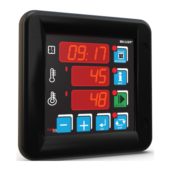
Panel operatorski Zegar RTC/Czas procesu Klawisz trybu AUTOSTART Temperatura kotła Kanał 1 Klawisz trybu INFO Syngalizacja pracy regulatora Klawisz trybu START Tempreatura batonu Kanał 2/naliczona liczba pasteryzacyjna Indu-50 | Version 1.91(85) Panel operatorski... -
Page 10: Opis Działania
W zależności od parametru ustawionego w komórce SF47 Setup: Przy wyborze HMD - godzina, minuta startu procesu z podaniem opóźnienia dobowego • Przy wyborze HM - ilość godzin i minut do startu procesu • Opis działania Indu-50 | Version 1.91(85) - Page 11 Na wyświetlaczu jest wyświetlona ilość godzin i minut jakie pozostały do zakończenia procesu. (*) - gdy wyliczana jest liczba pasteryzacyjna (**) - gdy ustawiony typ regulatora 4 dla kanału 3 Indu-50 | Version 1.91(85) Opis działania...
- Page 12 Powyższe funkcje są dostępne po podaniu kodu dostępu. W celu wyłączenia sprawdzania kodu dostępu należy jego wartość ustawić na zero. Standardowo kod dostępu do funkcji serwisowych dostępnych dla użytkownika jest wyłączony. Opis działania Indu-50 | Version 1.91(85)
- Page 13 W celu aktywowania alarmów należy w pierwszej kolejności dobrać czas do zadziałania alarmu [sekundy] w SETUP (komórki SF71..SF73), a następnie aktywować wybrane alarmy w SETUP (komórki SF60..SF70). Wystąpienie Alarmu należy potwierdzić klawiszem Jeżeli przyczyna wystąpienia alarmu nie została usunięta sterwonik po upływie czasu opóźnienia ponownie zasygnalizuje alarm. Indu-50 | Version 1.91(85) Opis działania...
-
Page 14: Pasteryzacja
Warunek zakończenia trybu START - ustawić na 19 lub 20. Wartość liczby pasteryzacyjnej określa się w Setup SF76. DZIAŁANIE REGULATORÓW Opis parametrów Temperatura zadziałania regulatora; do tej temperatury wyjście jest wysterowane (grzanie). Po osiągnięciu tej temperatury rozpoczyna się wykonanie algorytmu regulacji. Dout Stan na wyjściu cyfrowym (stan wysoki odpowiada załączeniu grzałek) Czas Pasteryzacja Indu-50 | Version 1.91(85) -
Page 15: Wykresy Regulatorów
UWAGA: Ten typ regulatora jest dostępny tylko na kanale 3 (ustawienie komórki SF31). (*) - typy regulatorów ustawiane dla poszczególnych kanałów w komórkach SETUP SF29, 30, 31 Indu-50 | Version 1.91(85) Typy regulatorów... -
Page 16: Dochodzenie Temperatury
W drugim obszarze, powyżej temperatury Tza realizowany jest algorytm dochodzenia temperatury do wartość i zadanej. W trzecim obszarze utrzymywana jest temperatura pomiędzy dolną i górną histerezę. Regulator „dochodzenia temperatury” (*) - typy regulatorów ustawiane dla poszczególnych kanałów w komórkach SETUP SF29, 30, 31 Typy regulatorów Indu-50 | Version 1.91(85) -
Page 17: Dobór Nastaw Regulatora Pid
. Wyjście z trybu edycji klawiszem Regulacja odbywa się w oparciu o: To - okres próbkowania Pr - wzmocnienie członu proporcjonalnego Ti - stała całkowania (czas zdwojenia) Td - stala różniczkowania (czas wyprzedzenia) Ts - temperatura zadana Indu-50 | Version 1.91(85) Dobór nastaw regulatora PID... -
Page 18: Setup Sterownika
Wartość odpowiadająca 20 mA dla kanalu 3 dla 0..20 mA SF11 0°C -99,0..999°C Wartość odpowiadająca 4 mA dla kanalu 1 dla 4..20 mA SF12 200°C -99,0..999°C Wartość odpowiadająca 20 mA dla kanalu 1 dla 4..20 mA Setup sterownika Indu-50 | Version 1.91(85) - Page 19 Histereza dolna dla kanału 1 SF33 1,0°C 0,0..5,0°C Histereza dolna dla kanału 2 SF34 1,0°C 0,0..5,0°C Histereza dolna dla kanału 3 SF35 1,0°C 0,0..5,0°C Histereza górna dla kanału 1 SF36 1,0°C 0,0..5,0°C Histereza górna dla kanału 2 Indu-50 | Version 1.91(85) Setup sterownika...
- Page 20 Jednostka temperatury SF52 1 [min] 0..99 [min] Czas trwania sygnału dźwiękowego Uwaga! Gdy wpisana wartość kasowanie sygnału klawiszem OK.! SF53 0 .. 1 Tryb pracy wyjścia alarmowego 0 - sygnał przerywany 1 - sygnał ciągły Setup sterownika Indu-50 | Version 1.91(85)
- Page 21 4 - blokowanie klawiatury gdy rozwarte wejścia 7-8 SF71 0..999 sek Czas opóźnienia sygnallzacji alarmu gdy uszkodzone czujniki SF72 0..999 sek Czas opóźnienia sygnallzacji alarmu gdy przekroczone dopuszczalne temperatury SF73 0..999 sek Czas opóźnienia sygnallzacji alarmu gdy alarm na wejściach kontrolnych Indu-50 | Version 1.91(85) Setup sterownika...
- Page 22 1 - kanał pomiarowy 2 2 - kanał pomiarowy 3 SF85 -50,0..100°C Przesunięcie temperatury zadanej dla regulatora 1 SF86 -50,0..100°C Przesunięcie temperatury zadanej dla regulatora 2 SF87 -50,0..100°C Przesunięcie temperatury zadanej dla regulatora 3 Setup sterownika Indu-50 | Version 1.91(85)
- Page 23 Czas przedmuchu - Regulator PID3 SF103 10 s 0..99,9 Wzmocnienie regulatora względnego SF104 15 s 0..120 s Minimalny czas załączenia palnika dla regulatora względnego SF105 15 s 0..120 s Minimalny czas załączenia palnika dla regulatora względnego Indu-50 | Version 1.91(85) Setup sterownika...
-
Page 24: Przekaźniki
REL 2 Wyjście przekaźnikowe regulatora 2 może być w całości lub części traktowany jako projekt układu sterowania. REL 3 Wyjście przekaźnikowe regulatora 3 REL 4 Włączany w trybie START REL 5 Alarm Przekaźniki Indu-50 | Version 1.91(85) -
Page 25: Przykładowa Aplikacja
Przykładowa aplikacja Indu-50 | Version 1.91(85) Przykładowa aplikacja... -
Page 26: Warunki Zakończenia Cyklu
Koniec cyklu po osiągnięciu czasu zadanego i po spadku temperatury płaszcza poniżej wartości zadanej SF45=19 Koniec cyklu po osiągnięciu liczby pasteryzacyjnej SF45=20 Koniec cyklu po osiągnięciu liczby pasteryzacyjnej lub po osiągnięciu zadanego czasu SF45=21 Koniec cyklu gdy po osiągnięciu temperatury batonu, zostanie odliczony czas zadany Warunki zakończenia cyklu Indu-50 | Version 1.91(85) -
Page 27: Najczęściej Zadawane Pytania (Faq)
Sprawdź adresy w sieci RS485. Uwaga! Adres każdego urządzenia musi być unikalny. • Nie działa czujnik temperatury PT-100, PT-500 lub PT-1000 Sprawdź poprawność ustawień dla podpiętego czujnika temperatury np. dla pierwszego czujnika PT-100 należy • ustawić w komórce SF2 wartość 1. Indu-50 | Version 1.91(85) Najczęściej zadawane pytania (FAQ) -
Page 28: Deklaracja Zgodności
Members States zmiany 91/263/EWG relating to electromagnetic comatibility 92/31/EWG 93/68/EWG Miejscowość: Czeladź dnia: 08.01.2019 (nazwisko i funkcja podpisującego upoważnionego do reprezentowania producenta lub upełnomocnionego przedstawiciela) wiecej informacji na stronach internetowych firmy Mikster www.mikster.pl podpis Deklaracja zgodności Indu-50 | Version 1.91(85) -
Page 29: Dane Techniczne
10 dni Typ regulatora: 2 typy regulatora dwustanowego i regulator PID. Warunkowe zakończenie procesu, programowane w SETUP. Rejestracja wartości zmierzonych: ok. 100 000 rejestracji. zależnie od wersji, patrz opis z tyłu urządzenia Indu-50 | Version 1.91(85) Dane techniczne... -
Page 30: Cechy Funkcjonalne
Bardzo mała Dwa sposoby silikonowa głębokość montażu urządzenia uszczelka montażowa Wodoodporność* Odporność na chemikalia** Odporność na działanie alkoholu** * od czoła IP 65 ** od czoła odporność na silne środki czyszczące w przemyśle spożywczym Cechy funkcjonalne Indu-50 | Version 1.91(85) -
Page 31: Notatki
Notatki Indu-50 | Version 1.91(85) Notatki... -
Page 32: Karta Gwarancyjna
Gwarancja nie obejmuje uszkodzeń powstałych podczas transportu. Karta gwarancyjna jest ważna z dowodem sprzedaży. Serwis wyrobów firmy Mikster Sp. z o.o. realizuje firma: MIKSTER SERVICE S.C. adres: 41-250 Czeladź, ul. Wojkowicka 21 tel. (32) 763 77 77 fax. (32) 763 75 94 pieczęć Czeladź,... - Page 33 Industrial Microprocessor Controller INDU-50 User’s Manual v. 1.8 | EN...
- Page 34 Contents Introduction The most frequently asked questions (FAQ) Components Declaration of Conformity Assembly Technical data Start up Features Operator panel Notes Operation description Guarantee card Pasterisation Guarantee conditions Governor diagrams Temperature approaching Selection of governor setup ID Controller setup Relays Example of application Cycle end conditions...
-
Page 35: Introduction
Introduction We would like to congratulate You the selection of the Industrial Microprocessor Controller INDU-50. We hope that You will find our product to be reliable and easily operated. Please read carefully the User’s manual. This will enable You to obtain the best effects in using the system and to prolong the service life of devices. -
Page 36: Components
Components The INDU-50 consists of the following elements: Legend Industrial Microprocessor Controller INDU-50 Clamping elements - 4 items Mask elements - 6 items Clamping screw - 10 items CD with Monitor lndu software User’s manual Plug AKZ950x14 - 1 item, Plug AKZ950x12 - 1 item, Plug AKZ950x2 - 1 item. -
Page 37: Assembly
Assembly power supply 230 V (option 24 V) rack mount opening Silicon washer should be lubricated by technical vaseline. Be aware that the washer should accurately adhere to the assembling surface. Indu-50 | Version 1.91(85) Assembly... -
Page 38: Start Up
ATTENTION: In case of power failure the controller saves in memory its current operating mode and when power is back, it returns to the same mode (unless time set in cell 48 - Setup has passed). Start up Indu-50 | Version 1.91(85) -
Page 39: Operator Panel
Operator panel RTC/CLOCK Process time AUTOSTART mode key Boiler temperature - Channel 1 INFO mode key Bar temperature - Channel 2 START mode key Meat-bar temperature Channel 2/counted pasterisation number Indu-50 | Version 1.91(85) Operator panel... -
Page 40: Operation Description
According to the setting in the Setup menu, item SF47: For HMD - hour, minute and daily delay when the START mode is to be activated • For HM - hours and minutes to the START mode • Operation description Indu-50 | Version 1.91(85) - Page 41 For typical controller settings after switching into the START mode all regulators are activated and the process time counting down is started. The time in hours and minutes to the process end is shown on the display. Indu-50 | Version 1.91(85) Operation description...
- Page 42 The functions mentioned above are available after the access code is entered. To disable the access code verification function, set access code at 0000 for the user’s function. Operation description Indu-50 | Version 1.91(85)
- Page 43 SETUP (items SF60..SF70). Any alarm shall be acknowledged by pressing If the cause of alarm has not been cleared, then the controller activates the alarm once again after activation delay time. Indu-50 | Version 1.91(85) Operation description...
-
Page 44: Pasterisation
Temperature of governor activation; Output is controlled up to this temperature (warming). When this temperature is reached the algorithm of regulation begins. Dout State on digital output (high state means that heaters are switched on). Time Pasterisation Indu-50 | Version 1.91(85) -
Page 45: Governor Diagrams
Governor diagrams Governor - simple histeresis Governor - reversed histeresis Governorr PI Indu-50 | Version 1.91(85) Governor diagrams... -
Page 46: Temperature Approaching
Above the Tza temperature, in the second zone, the algorithm of temperature approaching the set value is realised. In the third zone the temperature in between the lower and upper histeresis is kept. Governor of temperature approaching Temperature approaching Indu-50 | Version 1.91(85) -
Page 47: Selection Of Governor Setup Id
Regulation is being done on the basis of: To - sampling period Pr - strengthening of a proportional element Ti - integration constant (doubling time) Td - difentiation constant (advancing time) Ts - set temperature Indu-50 | Version 1.91(85) Selection of governor setup ID... -
Page 48: Controller Setup
Value correspondine to 4 mA for channel 1 4 .. 20 mA input SF12 200°C -99,0..999°C Value corresponding to 20 mA for channel 1 4 •• 20 mA input SF13 0°C -99,0..999°C Value corresoondine to 4 mA for channel 2 4 .. 20 mA input Controller setup Indu-50 | Version 1.91(85) - Page 49 Low hysteresis for channel 2 SF34 1,0°C 0,0..5,0°C Low hysteresis for channel 3 SF35 1,0°C 0,0..5,0°C High hysteresis for channel 1 SF36 1,0°C 0,0..5,0°C High hysteresis for channel 2 SF37 1,0°C 0,0..5,0°C High hysteresis for channel 3 Indu-50 | Version 1.91(85) Controller setup...
- Page 50 0 .. 1 Alarm output operating mode 0 - interrupted signal 1 - continuous signal SF54 150°C -99..999°C Maximum allowable (alarm) temperature for channel 1 SF55 150°C -99..999°C Maximum allowable (alarm) temperature for channel 2 Controller setup Indu-50 | Version 1.91(85)
- Page 51 Temperature exceeded alarm indication delay SF73 0..999 sec Control input alarm indication delay SF74 0..999 SETUP access code change Value 0 - code check OFF SF75 0..1 Time base for START mode 0 - hour:min 1 - min:sec Indu-50 | Version 1.91(85) Controller setup...
- Page 52 2 - measuring channel 3 SF85 -50,0..100°C Shifting of the set temperature for governor 1 SF86 -50,0..100°C Shifting of the set temperature for governor 2 SF87 -50,0..100°C Shifting of the set temperature for governor 3 Controller setup Indu-50 | Version 1.91(85)
-
Page 53: Relays
REL 2 Relay output of governor 2 system design. REL 3 Relay output of governor 3 REL 4 Switched on in START mode REL 5 Alarm Indu-50 | Version 1.91(85) Relays... -
Page 54: Example Of Application
Example of application Example of application Indu-50 | Version 1.91(85) -
Page 55: Cycle End Conditions
End of a cycle, when the pasterisation number is reached SF45=20 Koniec cyklu po osiągnięciu liczby pasteryzacyjnej lub po osiągnięciu zadanego czasu SF45=21 End of a cycle, when either the pasterisation number or the set time is reached Indu-50 | Version 1.91(85) Cycle end conditions... -
Page 56: The Most Frequently Asked Questions (Faq)
Check addresses in RS485 network. Attention! Each device must have an individual address. • Temperature sensor PT-100, PT-500 or PT-1000 does not operate. Check the setting correctness for the temperature sensor, e.g. for the first sensor, PT-100, value 1 should be set in • cell SF2. (FAQ) Indu-50 | Version 1.91(85) -
Page 57: Declaration Of Conformity
93/68/EWG City: Czeladź date: 08.01.2019 (the surname and function of the person undersigning who is authorized to represent the Producer or duly empowered representative) more information you can find on website www.mikster.pl seal Indu-50 | Version 1.91(85) Declaration of Conformity... -
Page 58: Technical Data
-10°C..+55°C Conditional process termination programmed in the SETUP menu. Storage temperature: -15°C..+60°C Recording up to approx. 100000 Enclosure size: 134x134x65 mm setpoints and measurements*. Rack mount opening: 90x90 mm * recording module (version R) Technical data Indu-50 | Version 1.91(85) -
Page 59: Features
Two ways of panel Dual silicon gasket Small depth mounnting Water proof* Chemical proof** Alcohol proof** * from the front IP 65 ** from the front - the resistance to strong cleaning agents used in the food industry Indu-50 | Version 1.91(85) Features... -
Page 60: Notes
Notes Features Indu-50 | Version 1.91(85) -
Page 61: Guarantee Card
Guarantee Certificate is valid together with the sale receipt. Servicing of the Mikster Sp. z o.o. products is realized by the MIKSTER SERVICE S.C. adres: 41-250 Czeladź, ul. Wojkowicka 21 tel. (32) 763 77 77 fax. (32) 763 75 94 seal date: Indu-50 | Version 1.91(85) - Page 62 MIKSTER SP. Z O.O. Wojkowicka 21, 41-250 Czeladź, Poland info@mikster.pl www.mikster.eu +48 32 763 77 77 VAT ID: PL9542113188 REGON: 273545050...
Need help?
Do you have a question about the INDU-50 and is the answer not in the manual?
Questions and answers