Table of Contents
Advertisement
Quick Links
MIKSTER
ul.Wojkowicka 21
R
41-250 CzeladŸ
www.mikster.com
Guarantee card
INDUSTRIAL MICROPROCESSOR CONTROLLER
serial no:
sale date:
............................................
The hereby given guarantee confirms the good quality and operation of the product.
The guarantee is furnished for 12 month period from the sale date.
The guarantee imposes an obligation of removing, free of charge, defects of the sold
product - in 14 days from the date of delivering the product for repairs – on the producer.
GUARANTEE CONDITIONS
Exploitation of the device should be done according to the Service Instruction and
according to its destination.
The guarantee loses its validity in the following cases:
»
rupture of laden seal,
»
mechanical damages,
»
damages caused by misapplication,
»
corrections in the guarantee certificate – unless they are introduced by the
producer himself.
Guarantee Certificate is valid together with the sale receipt.
Servicing of the Mikster Sp. z o.o. products is realized by the
MIKSTER SERVICE S.C. Company.
tel. +48 (32) 763 77 77
fax. +48 (32) 763 75 94
info@mikster.com
INDU-50
seal
Logginet
User's Manual
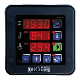
Industrial Microprocessor Controller INDU-50
v. 1.4
www.mikster.com
R
INDUSTRIAL TECHNOLOGY
Advertisement
Table of Contents

Related Manuals for Mikster INDU-50


Summary of Contents for Mikster INDU-50
- Page 1 – unless they are introduced by the producer himself. Guarantee Certificate is valid together with the sale receipt. User's Manual Servicing of the Mikster Sp. z o.o. products is realized by the MIKSTER SERVICE S.C. Company. Industrial Microprocessor Controller INDU-50 seal v.
-
Page 2: Table Of Contents
MIKSTER List of contents Introduction We would like to congratulate You the selection of the Industrial Microprocessor Controller INDU-50. Introduction.......................3 We hope that You will find our product to be reliable and easily operated. Please read carefully the User's Components.......................4 manual. -
Page 3: Components
MIKSTER MIKSTER Components Assembly The INDU-50 consists of the following elements: 65mm 134mm 90mm 09:52 AUTO/START 25.7 INFO INFO 23.4 09:52 START/STOP AUTO/START AUTO/START 25.7 indu EDIT EDIT INFO 23.4 START/STOP indu EDIT EDIT 80mm 90 mm 9 10 11 12 13 14... -
Page 4: Start Up
(unless time set in cell 48 – Setup has passed). – Channel 1 mode key INFO 23.4 Bar temperature START/STOP – Channel 2 START mode key indu Meat-bar temperature EDIT Channel 2/ counted pasterisation number Indu-50 version: 1.4 Indu-50 version: 1.4... -
Page 5: Info Mode
For HMD – hour, minute and daily delay when the START mode is to be activated process time counting down is started. For HM – hours and minutes to the START mode The time in hours and minutes to the process end is shown on the display. Indu-50 version: 1.4 Indu-50 version: 1.4... -
Page 6: Service Functions Accessible For The User
The functions mentioned above are available after the access code is entered. To disable the access code verification function, set access code at 0000 for the user’s function. Indu-50 version: 1.4 Indu-50 version: 1.4... -
Page 7: Pasterisation
Tza – temperature of governor activation; Output is controlled up to this temperature (warming). When this temperature is reached the algorithm of regulation begins. Dout – state on digital output (high state means that heaters are switched on). t- time Governorr PID Indu-50 version: 1.4 Indu-50 version: 1.4... -
Page 8: Temperature Approaching
Regulation is being done on the basis of: EDIT Dout To – sampling period Pr – strengthening of a proportional element Governor of temperature approaching Ti - integration constant (doubling time) Td – difentiation constant (advancing time) Ts - set temperature Indu-50 version: 1.4 Indu-50 version: 1.4... -
Page 9: Controller Setup
3 4..20 mA input For “setpoint ramping” algorithm SF16 -99,0 .. 999 C Value corresponding to 20 mA for channel 3 4..20 mA input SF42 0..100 sek Regulator activation delay [seconds] for channel 1 Indu-50 version: 1.4 Indu-50 version: 1.4... - Page 10 On / Off aximum allowable (alarm) temperature for channel 2 SF81 52 C 0..100 C Temperature, from which the governor starts counting the pasterisation number SF68 On / Off aximum allowable (alarm) temperature for channel 3 Indu-50 version: 1.4 Indu-50 version: 1.4...
-
Page 11: Relays
REL4 Switched on in START mode REL5 Alarm Pic1. this example is given for informative purpose only and should not be considered in part or in whole as a system design. HEATING JACKET Pic.1 HEAT EXCHANGER Indu-50 version: 1.4 Indu-50 version: 1.4... -
Page 12: Cycle End Condition
Check the setting correctness for the temperature sensor, e.g. for the first sensor, PT-100, value 1 SF45=19 End of a cycle, when the pasterisation number is reached. should be set in cell SF2. SF45=20 End of a cycle, when either the pasterisation number or the set time is reached. Indu-50 version: 1.4 Indu-50 version: 1.4... -
Page 13: Declaration Of Conformity
: -30.. +400 C identification: ° - accuracy 0.1 C Industrial Microprocessor Controller INDU-50 - 5 relay outputs - 1 x RS-485 Conforms with the provisions of the following EC directive (directives). - 2 control inputs (for indicating alarms) ±... -
Page 14: Features
Two ways of panel Small depth mounnting Water proof * Chemical proff ** Alcohol proff ** from the front IP 65 from the front - the resistance to strong cleaning agents used in the food industry Indu-50 version: 1.4 Indu-50 version: 1.4...
Need help?
Do you have a question about the INDU-50 and is the answer not in the manual?
Questions and answers