
Related Manuals for Mikster INDU WRC-2010H


Summary of Contents for Mikster INDU WRC-2010H
- Page 1 1.07 INDU WRC-2010H Controller User’s Manual Sp. z o.o. 41-250 Czeladź, ul. Wojkowicka 21 Tel. 0 32 763–77–77 Fax: 0 32 763–75–94 www.mikster.pl e-mail: info@mikster.pl v1.07 29.05.2008...
-
Page 2: Table Of Contents
TABLE OF CONTENTS page 1. STRUCTURE, APPLICATIONS, POTENTIAL .....................4 2. “INDU WRC-2010H” - CONTROL PANEL......................4 3. “INDU WRC-2010H” - START OF OPERATION ....................6 4. PROCESS PROGRAMS ............................6 4.1. Manufacturing process programming......................6 4.2. Execution of program stored in memory .......................8 4.3. Program execution interruption ........................9 4.4. - Page 3 INDU WRC-2010H Controller – User’s Manual ver. 1.07 V. INDU WRC RO-01 MODULE ..........................42 1. MODULE ASSEMBLING ............................42 2. MODULE FUNCTIONS ............................42 3.FIGURE................................42 4. TECHNICAL DATA.............................43 5. C :........................43 ARDS ADDRESSING IN THE SYSTEM VI. INDU WRC TO-01 MODULE ..........................44 1.
-
Page 4: Structure, Applications, Potential
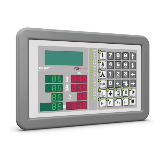
INDU WRC-2010H Controller – User’s Manual ver. 1.07 1. STRUCTURE, APPLICATIONS, POTENTIAL The INDU WRC-2010H Controller is a unit designed to control those industrial processes, in which temperature is the most important element, such as: smoke-chambers, brewing boilers, defrosting chambers, etc. Smoke- chamber control is the main purpose, for which this controller has been built, and this is reflected in the type of data being shown, controller operation procedure, etc. - Page 5 INDU WRC-2010H Controller – User’s Manual ver. 1.07 1. Numeric display keypad 2. Graphic display 4. Signaling diodes 3. Numeric keys with function keys Fig. 1 The INDU WRC-2010H Controller “control panel” - 5- 29.05.2008...
-
Page 6: Indu Wrc-2010H" - Start Of Operation
INDU WRC-2010H Controller – User’s Manual ver. 1.07 3. “INDU WRC-2010H” - START OF OPERATION As soon as power is turned on, all numeric displays and diodes will light, and graphic display will show “WRC 2000 Init”. After some time displays and diodes will be switched off, which proves correct work of the system. The controller will switch to stand-by mode. - Page 7 INDU WRC-2010H Controller – User’s Manual ver. 1.07 selected program blinks press “Enter” key to edit the program first enter program name (enter letter in position by pressing key with selected letter as many times as required, move to next position by pressing right arrow press “Enter”...
-
Page 8: Execution Of Program Stored In Memory
INDU WRC-2010H Controller – User’s Manual ver. 1.07 enter preset bar temperature and press “Enter” enter preset humidity and press “Enter” shift between data you are entering with arrows this ends editing of a single process; if you wish to edit another cycle, enter its number and then proceed as before, whereas if all cycles in a given program have been edited, then press “Stop”... -
Page 9: Program Execution Interruption
Manual). 4.4. Automatic process activation The INDU WRC-2010H Controller allows to activate a program at any previously set hour. Follow the procedure below to allow for automatic activation of the controller: press “Clock”... - Page 10 INDU WRC-2010H Controller – User’s Manual ver. 1.07 enter process start date (current date is prompted by default) press “Start” graphic display will show program name, date and program activation time, as well as current date and time, the lamp at “Clock” key will go on At specified hour the controller will automatically start execution of appropriate program from the first step.
-
Page 11: Editing Of Parameters Set During Controller Operation
INDU WRC-2010H Controller – User’s Manual ver. 1.07 4.5. Editing of parameters set during controller operation It is possible to correct previously set parameters while the controller executes a program. Follow the procedure below (during program execution) to do that: press “Configuration”... -
Page 12: Controller Configuration
INDU WRC-2010H Controller – User’s Manual ver. 1.07 5. CONTROLLER CONFIGURATION The controller possesses very highly developed configuration functions, which allow to adjust its parameters and way of working to user’s individual needs. Suitable settings entered through the configuration menu are stored in the controller memory and used during its work. -
Page 13: User's Functions
INDU WRC-2010H Controller – User’s Manual ver. 1.07 5.1. User’s functions These functions allow to set the following: time and date menu language so far other functions are inactive 5.1.1. Time and date setting Follow the procedure below to set time and date: - select function “Set clock”... - Page 14 INDU WRC-2010H Controller – User’s Manual ver. 1.07 press “Enter” select one of 4 languages using arrow keys “left” - “right” press “Enter” 4 languages are available: Polish English two languages defined by user and transferred to the controller via PC computer – instruction how to do this is enclosed to the program for PC.
-
Page 15: Service Functions 1
INDU WRC-2010H Controller – User’s Manual ver. 1.07 5.2. Service functions 1 In these functions it is possible to set the following: controller parameters step parameters alarms STOP and PAUSE mode parameters, and parameters of key functions F1..F4 I/O output parameters washing parameters 5.2.1. - Page 16 INDU WRC-2010H Controller – User’s Manual ver. 1.07 Repeat the procedure shown before until required values are set in each cell. The table below shows the meaning of individual cells: CELL CELL NAME FACTORY-SET RANGE DESCRIPTION VALUE F 01 ADDRESS FOR PC 1..32...
- Page 17 INDU WRC-2010H Controller – User’s Manual ver. 1.07 F 10 DELTA STATUS 0..2 0 - "delta" OFF, 1 - delta bar-chamber, 2 - "delta" temperature rise in time REC. FREQ. 0..99 Recording frequency F 11 TIME FOR RESTART 0..200 F 12 MAX.
- Page 18 INDU WRC-2010H Controller – User’s Manual ver. 1.07 F 32 TYPE OF DIGIT.INPUT 0..1 Type of voltage delivered to control inputs: 0 – constant voltage 1 – variable voltage STAT. REL.FOR END 0..1 Type of input signal for cycle termination...
- Page 19 INDU WRC-2010H Controller – User’s Manual ver. 1.07 ADDITIONAL SET 0..1 Additional set1 and additional set2 during program editing NOT USED NOT USED NOT USED MAX CARD ERROR 0..9 Maximum card error WEITHT TAR. 0..3 0-tare off 1-tare on F4 pressed...
-
Page 20: Setting Of Step Parameters
INDU WRC-2010H Controller – User’s Manual ver. 1.07 5.2.2. Setting of step parameters Each process controlled by INDU WRC-2010H consists of steps executed in a sequence. The controller may store settings for 16 steps. Define the following elements for each step: name... - Page 21 INDU WRC-2010H Controller – User’s Manual ver. 1.07 - then, using arrow “up” , switch on relay , or, using arrow “down” , switch off relay - after having set statuses of all relays press “Stop” key select function “Step end”...
-
Page 22: Alarm Setting
INDU WRC-2010H Controller – User’s Manual ver. 1.07 TIR>TIS OR TCR<TCS cycle end after reaching preset time value, or after drop of temperature in bar below preset value TIR>TIS OR HUR<HUS cycle end after reaching preset time value, or after drop of humidity below preset value TIR>TIS AND... - Page 23 INDU WRC-2010H Controller – User’s Manual ver. 1.07 logics of outputs alarm status Follow the procedure below to set alarm parameters: select function “Alarm settings” press “Enter” the list of all alarms will be displayed select an alarm to set its parameters and press “Enter”...
- Page 24 INDU WRC-2010H Controller – User’s Manual ver. 1.07 and press “Enter” enter time, after which the controller should react to alarm occurrence time is given in seconds press “Enter” - “Alarm output logics” and press “Enter” - this function specifies how to link status preset in function “Outputs when alarm” with relays;...
- Page 25 INDU WRC-2010H Controller – User’s Manual ver. 1.07 “Alarm off” – symbol - the controller will ignore particular alarm “Process interruption” – symbol - if the controller is in process execution phase and an alarm will occur, the process will be interrupted “Process continuation”...
-
Page 26: Parameter Setting For Pause Mode, Stop Mode And Key Functions F1
INDU WRC-2010H Controller – User’s Manual ver. 1.07 5.2.4. Parameter setting for pause mode, stop mode and key functions F1..F4 The controller has two special modes: stop and pause; you may set the following for each of them: which outputs are to be active... -
Page 27: I/O Output Parameter Setting
INDU WRC-2010H Controller – User’s Manual ver. 1.07 press “Stop” - “End time ...” and press “Enter” enter time, after which function or mode operation will be terminated – in seconds press “Enter” - “Output logics ...” and press “Enter”... - Page 28 INDU WRC-2010H Controller – User’s Manual ver. 1.07 Follow the procedure below to set these parameters: select function “Parameters of outputs 0/1” press “Enter” the list of all relays will be displayed select the relay to se tits parameters, and press “Enter”...
- Page 29 INDU WRC-2010H Controller – User’s Manual ver. 1.07 Time Ta - delayed deactivation Time Ta - pulse generator Wyłączony Time Ta Time Tb Time Ta Time Tb then set times Ta and Tb – time value is given in seconds...
- Page 30 INDU WRC-2010H Controller – User’s Manual ver. 1.07 O ffse t ¼ O k n o Window O k n o Z A D ½ O k n o Window O k n o Window Z A Ł W Y Ł...
-
Page 31: Washing Parameter Setting
INDU WRC-2010H Controller – User’s Manual ver. 1.07 5.2.6. Washing parameter setting The “Washing” program (described later in this manual) is executed on the basis of special process steps, for which parameters are set independently of process steps used in regular programs. -
Page 32: Key Test
INDU WRC-2010H Controller – User’s Manual ver. 1.07 5.3.2. Key test Follow the procedure below to test correct operation of keys: select function “T2” press “Enter” The display of “chamber temperature set value” shows the number attributed to the key pressed last; if any other key is pressed, displayed number will be changed. -
Page 33: Washing
“Washing” is a special program hidden in the controller memory, independent of any other programs, and based on dedicated process steps, which is activated in a special way. According to its name, it is designed for automatic washing of units controlled by INDU WRC-2010H. 5.4.1. Washing programming Follow the procedure below to set the “Washing”... -
Page 34: Additional Information
The values can be checked at „Stop” as well as during the program operation. 7. HOW TO CONNECT THE CONTROLLER TO PC COMPUTER KRAKOWSKA SUSZENIE 1/ 3 2/ 3 023 75 6 Fig. No. 2 INDU WRC-2010H Controller connection to PC computer - 34- 29.05.2008... -
Page 35: Technical Data
INDU WRC-2010H Controller – User’s Manual ver. 1.07 8. TECHNICAL DATA OVERALL DIMENSIONS: Width 182 mm Height 324 mm 12-24 V DC POWER SUPPLY: CASING: Single-element, “FRONT PANEL”-type from front IP 65 PROTECTION DEGREE: 0..75 % (relative humidity) HUMIDITY: -20..+70 °C... -
Page 36: Indu Wrc Cpu-01 Module
INDU WRC-2010H Controller – User’s Manual ver. 1.07 II INDU WRC CPU-01 MODULE 1. MODULE ASSEMBLING Module should be assembled on a rail and then connected with other modules by a belt (module of the power supply PS01 is necessary for the module operation).Description of outputs for RS485 is on the casing. The upper connection RS A B is connected to the converter in the Rennon Slicer panel.Communication with the... -
Page 37: Technical Data
INDU WRC-2010H Controller – User’s Manual ver. 1.07 4. TECHNICAL DATA POWER SUPPLY: 5 V DC, 12 V DC Dimensions: 45x75x105 mm CASING: for assembling on a rail TS 35 EG45 from the Phoenix Contact Company PROTECTION DEGREE: IP 30 -40..+80 °C... -
Page 38: Indu Wrc Ai-01/6 Module
INDU WRC-2010H Controller – User’s Manual ver. 1.07 III. INDU WRC AI-01/6 MODULE 1. MODULE ASSEMBLING Module should be assembled on a rail and then connected with other modules by a belt. PT 100 PT 100 TEMP. TEMP. “SUCHY” “PŁYTY”... -
Page 39: Technical Data
INDU WRC-2010H Controller – User’s Manual ver. 1.07 4. TECHNICAL DATA POWER SUPPLY: 5 V DC, 12 V DC CASING: Dimensions: 45x75x105 mm for assembling on a rail TS 35 EG45 from the Phoenix Contact Company PROTECTION DEGREE: IP 30 -40..+80 °C... -
Page 40: Indu Wrc Di-01Module
INDU WRC-2010H Controller – User’s Manual ver. 1.07 IV. INDU WRC DI-01MODULE 1. MODULE ASSEMBLING Module should be assembled on a rail and then connected with other modules by a belt. 2. MODULE FUNCTIONS DI-01 module is a bistable input module, which serves for controlling input signals (e.g. failure control). -
Page 41: Technical Data
INDU WRC-2010H Controller – User’s Manual ver. 1.07 4. TECHNICAL DATA 5 V DC, 12 V DC POWER SUPPLY: CASING: Dimensions: 45x75x105 mm for assembling on a rail TS 35 EG45 from the Phoenix Contact Company PROTECTION DEGREE: IP 30 -40..+80 °C... -
Page 42: Indu Wrc Ro-01 Module
INDU WRC-2010H Controller – User’s Manual ver. 1.07 V. INDU WRC RO-01 MODULE 1. MODULE ASSEMBLING Module should be assembled on a rail and then connected with other modules by a belt. 2. MODULE FUNCTIONS Module serves for controlling by means of relay outputs. fan-out of a single output: 4A. -
Page 43: Technical Data
INDU WRC-2010H Controller – User’s Manual ver. 1.07 4. TECHNICAL DATA POWER SUPPLY: 5 V DC, 12 V DC CASING: Dimensions: 45x75x105 mm for assembling on a rail TS 35 EG45 from the Phoenix Contact Company IP 30 PROTECTION DEGREE: -40..+80 °C... -
Page 44: Indu Wrc To-01 Module
INDU WRC-2010H Controller – User’s Manual ver. 1.07 VI. INDU WRC TO-01 MODULE 1. MODULE ASSEMBLING Module should be assembled on a rail and then connected with other modules by a belt. 2. MODULE FUNCTION Module serves for controlling by means of transistor outputs. Fun-out of a single output 0.8A, total current of all outputs <... -
Page 45: Technical Data
INDU WRC-2010H Controller – User’s Manual ver. 1.07 4. TECHNICAL DATA POWER SUPPLY: 5 V DC, 12 V DC CASING: Dimensions: 45x75x105 mm for assembling on a rail TS 35 EG45 from the Phoenix Contact Company IP 30 PROTECTION DEGREE: -40..+80 °C... -
Page 46: Indu Wrc Com-01 Module
INDU WRC-2010H Controller – User’s Manual ver. 1.07 VII. INDU WRC COM-01 MODULE 1. MODULE ASSEMBLING Module should be assembled on a rail and then connected with other modules by a belt. 2. MODULE FUNCTION The module is used for communication between the INDU WRC set and the PC. Apart from storing the recordings the module enables readout of the set technological process parameters and values measured by controller’s... -
Page 47: Technical Data
INDU WRC-2010H Controller – User’s Manual ver. 1.07 4. TECHNICAL DATA POWER SUPPLY: 5 V DC, 12 V DC CASING: Dimensions: 45x75x105 mm for assembling on a rail TS 35 EG45 from the Phoenix Contact Company IP 30 PROTECTION DEGREE: -40..+80 °C... -
Page 48: Indu Wrc Ps-01 Module
INDU WRC-2010H Controller – User’s Manual ver. 1.07 VIII. INDU WRC PS-01 MODULE 1. MODULE ASSEMBLING Module should be assembled on a rail and then connected with other modules by a belt. 2. MODULE FUNCTION The module is used for supplying the INDU WRC controller. It is supplied by 24V AC. -
Page 49: Technical Data
INDU WRC-2010H Controller – User’s Manual ver. 1.07 4. TECHNICAL DATA POWER SUPPLY: 24V AC CASING: Dimensions: 45x75x105 mm for assembling on a rail TS 35 EG45 from the Phoenix Contact Company IP 30 PROTECTION DEGREE: -40..+80 °C TEMPERATURE: Storage: Operation: -20..+65 °C... - Page 50 INDU WRC-2010H Controller – User’s Manual ver. 1.07 Fig. Modules connection - 50- 29.05.2008...
- Page 51 INDU WRC-2010H Controller – User’s Manual ver. 1.07 - 51- 29.05.2008...
Need help?
Do you have a question about the INDU WRC-2010H and is the answer not in the manual?
Questions and answers