Table of Contents
Advertisement
Advertisement
Table of Contents

Related Manuals for Creality 3D Ender-5 S1


Summary of Contents for Creality 3D Ender-5 S1
- Page 1 Create reality,achieve dreams Ender-5 S1 Ender-5 S1 3D Printer User Manual V1.3...
- Page 2 To Our Dear Users Thank you for choosing Creality. To make using our products easier, please read this User Manual before you start and follow the instructions provided carefully. Creality is always ready to provide you with high-quality services. If you encounter any issues or have any questions when using our products, please use the contact information at the end of this manual to contact us.
- Page 3 Instructions for Use 1. Do not use this printer by methods or operations not described in this manual, otherwise it may result in accidental injury or property damage.; 2. Do not place this printer near flammable materials, explosive materials or high heat sources. Please place this printer in a ventilated, cool and low-dust environment.
-
Page 4: Table Of Contents
Contents 1. About the Printer · · · · · · · · · · · · · · · · · · · · · · · · · · · · · · · · · · · · · · · · · · · · · · · · · · · · · · · · · · · · · · · · · · · · · · · · · · · · · 01-01 2. -
Page 5: About The Printer
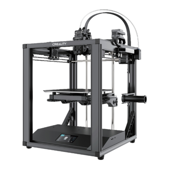
1. About the Printer Nozzle Assembly Material Rack Y-axis Motor Printing Platform Material Barrel Power Supply Dial-up Leveling Nuts Z-Axis Motor Z-axis Limit Switch Display Screen Type-C Port Power Switch X-axis Motor Storage Card Slot Filament Detection X-axis Limit Switch Handle Y-axis Limit Switch... -
Page 6: Equipment Specifications
2. Equipment Specifications Equipment Specifications Model Ender-5 S1 Modeling Technolog Modeling Dimensions 220*220*280mm Leveling Method Auto-leveling with CR-Touch Number of Nozzles 1pcs Extruder Diameter 0.4 mm (standard) Slice Thickness 0.05-0.35mm Precision ±0.1mm Typical Speed 120mm/s Printing Speed ≤ 250 mm/s Nozzle Temperature ≤... -
Page 7: Parts List
3. Parts List Base Component Top Component Printing Platform Z-axis Component Profile × 4 Platform L Support Assembly Platform R Support Assembly Diagonal Bracing Material Rack... -
Page 8: Accessory List
4. Accessory List Cutting Plier Nozzle Cleaner Blade Wrench and Screwdriver Power Cable Cable Tie × 5 Flexible Flat Storage Card Cable Clip × 5 & Card Reader Bending Harnesses Wire Clip (Blue) Filament (200g) Spare Nozzle Material Barrel Teflon Tube M5×30 Hexagon Socket M5×25 Hexagon Socket Head Cap Screw with S... -
Page 9: Assembling 3D Printer
5. Assembling 3D Printer 5.1 Install the Profile Align the profile progressively with the holes in the printer base according to the numerical label and pre-lock it individually using the No.25 screws first and then finally lock it all together. Tips: Please make sure that each profile is installed in the correct position. -
Page 10: Install The Top Component
5. Assembling 3D Printer 5.2 Install the Top Component Place the top component on top of the profile and pre-lock each of the four corners with No.25 screws before locking them all. M5×25 Hexagon Socket Head Cap Screw with Spring Washer × 8... -
Page 11: Install The Z-Axis Kit
5. Assembling 3D Printer 5.3 Install the Z-axis Kit Put the print platform component on the foam support and combine it with the Z-axis component to form a Z-axis kit, then fasten it with the No.25 screws. Z axis motor Tips: The foam in the box can be used as a support. - Page 12 5. Assembling 3D Printer 5.3 Install the Z-axis kit Place the Z-axis assembly upside down on the foam support, then fix the platform support to the linear bearing, and lock it with No.26 screws; B.Secure the other end of the platform support to the profile using No.27 screws to lock it in place. Z axis motor ②...
- Page 13 5. Assembling 3D Printer 5.3 Install the Z-axis Kit Tilt the Z-axis kit while placing the bottom inside the equipment frame profile.
- Page 14 5. Assembling 3D Printer 5.3 Install the X-axis Kit Hold the frame at an angle, push the Z-axis kit in and lift it between the top profile and the optical axis; Be sure that the bottom optical axis holder is located on the profile. Be placed between the top profile and the optical axis The optical axis holder is to be clamped...
- Page 15 5. Assembling 3D Printer 5.3 Install the Z-axis Kit Align the top of the Z-axis kit with the profile holes, pre-lock it first with the No.24 screws and then tighten all the screws. M5×30 Hexagon Socket Head Cap Screw with S pring Washer ×...
-
Page 16: Install The Diagonal Bracing
5. Assembling 3D Printer 5.4 Install the Diagonal Bracing Put two different diagonal bracing on the bottom of the profile and lock the ends to the profile using No.27 screws. Diagonal bracing M5×20 Hexagon Socket Head Cap Screw × 4... -
Page 17: Install The Material Rack
5. Assembling 3D Printer 5.5 Install the Material Rack After assembling and tightening the material barrel and bracket into a material rack, use the No.28 screws to secure and lock it to the profile. M5×14 Hexagon Socket Button Head Screw × 2... -
Page 18: Equipment Wiring
5. Assembling 3D Printer 5.6 Equipment Wiring Y axis motor X axis motor D.Connect the Y-axis motor cable to the Y-axis limit switch cable A.Connect the X-axis motor cable to the X-axis limit switch cable E.Connect the Z-axis motor cable to the Z-axis limit switch cable B.Connect the filament detection line;... -
Page 19: Install The Teflon Tube
5. Assembling 3D Printer 5.7 Install the Teflon Tube Insert one end of the Teflon tube into the interface of the Teflon tube fixing block, with the other end inserted through the snap to the bottom and finally into the blue jaws. -
Page 20: Fix The Flexible Flat Cable
5. Assembling 3D Printer 5.8 Fix the flexible flat cable To maintain a smooth alignment, please use flat cable clips and cable ties to secure the flat cables to the profile as shown in the diagram to avoid abnormal compression caused by printing interference and tangling during the operation of the device. Bending harnesses Cable Tie Flexible Flat Cable Clip ×... -
Page 21: Using The 3D Printer
6.Using the 3D Printer 6.1 Switch on the Power Please select the correct voltage mode according to the local grid voltage and then switch on the power. Please ensure the correct position for the power supply switch and mains before ●... -
Page 22: Auxiliary Leveling
6.Using the 3D Printer 6.2 Auxiliary Leveling Click on "Settings" and go to "Leveling Method"; Click on "Z-axis Homing" first, and then adjust the Z-axis compensation value when the nozzle returns to the center of the platform, to ensure that the nozzle is approximately 0.1mm from the platform, about the thickness of a piece of an A4 paper. >>... - Page 23 6.Using the 3D Printer 6.2 Auxiliary Leveling Click on the numbers 2, 3, 4 and 5 on the screen respectively to move the nozzle to the corresponding position, turn the leveling nut and adjust the printing platform so that it is in just the right position to fit the nozzle with a spacing of approximately 0.1mm; then level the four corners in sequence.
-
Page 24: Auto Leveling
6.Using the 3D Printer 6.3 Auto Leveling Click on "Settings", go to "Leveling Method", select "AUTO. LVL" and click on the "Start" button to start automatic leveling. >> Until auto leveling is 100% completed. -
Page 25: Printer Preheating
6.Using the 3D Printer 6.4 Printer Preheating Manual Temperature Setting: Select "Prepare", click on "Temperature Setting" and then manually set the temperature of the nozzle and hotbed based on the filaments used for printing. >>... - Page 26 6.Using the 3D Printer 6.4 Printer Preheating Auto Temperature Setting: select "Prepare", click on "Temperature Setting" and select "Preheat PLA" or "Preheat ABS" to preheat the nozzle and hotbed based on the material to be printed. >> Tips: 1、PLA Preheating Temperature: nozzle temperature 205°, hotbed temperature 60°; ABS preheating temperature: nozzle temperature 260°, hotbed temperature 90°.
-
Page 27: Filament Loading
6.Using the 3D Printer 6.5 Filament Loading Cut and straighten the front end of the filament at 45 degrees and place the tray on the material rack. Tips: How to Replace the Filament? Method 1. Withdraw the filaments quickly and feed the new filaments after the nozzle is preheated and filaments are pushed a little forward. Method 2. -
Page 28: Start Printing
6.Using the 3D Printer 6.6 Start Printing B.Go to Select language → Next → Select model → Next → Finish to Visit our official website (https://www.creality.com) to download complete the configuration. and install the software, or install the Creality software via the memory card provided with the printer. - Page 29 6.Using the 3D Printer 6.6 Start Printing D.Generate the G-code file → Save it to the memory card. E.Insert the memory card. >> Note: 1. For details on using the software, please refer to the slicing software user manual on the memory card. 2.
- Page 30 6.Using the 3D Printer 6.6 Start Printing Choose the file to be printed; Click on the Start Printing button; >> Already in printing status.
-
Page 31: Maintenance Instructions
7.Maintenance Instructions 7.1 Platform Plate Maintenance If there are residual filaments on the platform plate, If the first layer of the model is not properly glued, it is recommended to apply scrape them off lightly with a blade and print again. solid adhesive evenly on the surface of the platform plate before preheating for printing. -
Page 32: Lubrication Protection
7.Maintenance Instructions 7.3 Lubrication Protection You are recommended to purchase your own lubricating fluid for regular maintenance of the optical axis area. -
Page 33: Error Code Instructions
7.Maintenance Instructions 7.4 Error Code Instructions Error Code Instructions Parameters Hotend Thermal Runaway! Hotend Heating Failed! Hotend Thermistor Error! Hotbed Thermal Runaway! Hotbed Heating Failed! Hotbed Thermistor Error! E201 Timeout E202 Homing Failed E203 Probing Failed E204 Click Reboot In the event that any of the above problems arise and cannot be resolved: ①... -
Page 34: Circuit Wiring
8.Circuit Wiring Mainboard fan 30P flexible flat cable Storage card slot 10P flexible flat cable 24P flexible flat cable Hotbed thermistor port Hotbed DC 24V Model fan port Type-c port Fuse Heat sink fan port Heating pipes CR-Touch Z-Axis Motor Port Nozzle thermistor Extruder Filament detection port Z limit port Touch screen port Knob display screen port... - Page 35 Due to the differences between different machine models, the actual objects and the images can differ. Please refer to the actual machine. The final explanation rights shall be reserved by Shenzhen Creality 3D Technology Co., Ltd. SHENZHEN CREALITY 3D TECHNOLOGY CO., LTD.
Need help?
Do you have a question about the Ender-5 S1 and is the answer not in the manual?
Questions and answers
My Ender 5 S1 keeps rebooting when I try to print anything...sometime mid print, other times, when I simply try to set the bed temp
The reboots of your Creality Ender-5 S1 during printing or when setting the bed temperature could be caused by a firmware issue or a hardware problem, such as a power supply fault or a short circuit. Updating the firmware or checking for electrical issues like overheating, loose connections, or a faulty SD card may help resolve the problem.
This answer is automatically generated