Table of Contents
Advertisement
Quick Links
Advertisement
Table of Contents

Subscribe to Our Youtube Channel
Related Manuals for LS LSUM 051R3C 0166F EA


Summary of Contents for LS LSUM 051R3C 0166F EA
- Page 1 User Manual LSUM 051R3C 0166F EA www.lsmaterials.co.kr www.lsmaterials.co.kr...
- Page 2 User Manual LSUM 051R3C 0166F EA History Version Date Change Description Author SW Son 07 . Nov . 2016 First version SH Kim 26 . Nov . 2021 New format www.lsmaterials.co.kr www.lsmaterials.co.kr...
-
Page 3: Table Of Contents
User Manual LSUM 051R3C 0166F EA CONTENTS …………………………………… 1. Overview ………………..2. Identification of features ……………………………………. 3. Unpacking ……………………………………. 4. Safety 5. Module to module connection …………………….. …………………..6. Output terminal connection …………………….. 7. Output connector …………………………………..8. Mounting …….…………………………….. -
Page 4: Overview
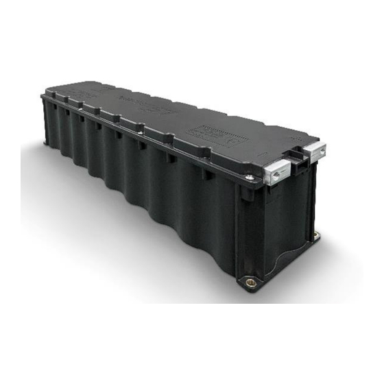
LSUM 051R3C 0166F EA 1. Overview The LS 51.3V / 166F Ultracapacitor Module has high energy and low ESR to meet energy storage and power delivery requirements. The cells used in the module have 2.85V maximum voltage rating and are connected in series to get higher operating voltage of modules. -
Page 5: Unpacking
User Manual LSUM 051R3C 0166F EA 3. Unpacking Inspect the shipping carton for signs of damage prior to unpacking the module. Damage to the shipping carton or module should be reported to the carrier immediately. Remove the module from the shipping carton and retain the shipping materials until the unit has been inspected and is determined to be operational. -
Page 6: Module To Module Connection
User Manual LSUM 051R3C 0166F EA 5. Module to module connection - There are series and parallel connection for High power <Fig. 2> Series Connection of Modules <Fig. 3> Parallel Connection of Modules. www.lsmaterials.co.kr www.lsmaterials.co.kr... -
Page 7: Output Terminal Connection
LSUM 051R3C 0166F EA 6. Output terminal connection The LS 51.3V / 166F Ultracapacitor Modules are designed to connect directly to a ring or a bus bar. The positive and negative terminals have each hole for the screw. The positive terminal threaded size is M8 and negative terminal is M10. Wave washers are required to ensure long term, reliable connections. - Page 8 User Manual LSUM 051R3C 0166F EA - The output of 4pin-connector is tabulated below. Pin # Pin out Signal Temp. pin#1 470Ω ± 50% @25℃ Temp. pin#2 H - normal Over Voltage Alarm L - Alarm * Resistance to temperature chart for the appendix I www.lsmaterials.co.kr...
- Page 9 User Manual LSUM 051R3C 0166F EA Pin 4 is connected with monitoring connector output signals receiver circuit’s ground. The output signals are isolated from the capacitor voltage and from chassis ground. The recommended voltage is 5V DC. When a cell in the module goes into over voltage condition, pin 3 has alarm signal.
-
Page 10: Mounting
User Manual LSUM 051R3C 0166F EA 8. Mounting The modules should not be mounted in locations where they are directly exposed to the environment. - <Fig. 6> shows the mounting positions of the module. <Fig. 6> Mounting Positions www.lsmaterials.co.kr www.lsmaterials.co.kr... -
Page 11: Maintenance
User Manual LSUM 051R3C 0166F EA 9. Maintenance Power Rating If the applied voltage is over rated voltage, charging the module should be stopped. And the allowable low voltage level of the module depends on the user’s requirements, but full discharging to 0V does not affect the module performance. - Page 12 User Manual LSUM 051R3C 0166F EA Appendix I www.lsmaterials.co.kr www.lsmaterials.co.kr...
- Page 13 User Manual LSUM 051R3C 0166F EA Appendix II www.lsmaterials.co.kr www.lsmaterials.co.kr...
Need help?
Do you have a question about the LSUM 051R3C 0166F EA and is the answer not in the manual?
Questions and answers