
Related Manuals for Still LTX Series


Summary of Contents for Still LTX Series
- Page 1 Original instructions LTX10, LTX20, LTX-T04 Tractor LTX- 1193 801 16 01 EN - 03/2022 - 10...
- Page 3 Internet address and QR code The information can be accessed at any time by pasting the address https://m.still.de/vdma in a web browser or by scanning the QR code. 1193 801 16 01 EN - 03/2022 - 10...
-
Page 5: Table Of Contents
Table of contents Foreword Your industrial truck ........... General . - Page 6 Table of contents Modifications and refitting ..........Medical equipment .
- Page 7 Table of contents Commissioning ............Emergency stop switch .
- Page 8 Table of contents Checking the battery charging status ........Opening the battery hood .
-
Page 9: Foreword
Foreword... -
Page 10: Your Industrial Truck
Foreword Your industrial truck Your industrial truck General The truck described in these operating instruc- tions corresponds to the applicable standards and safety regulations. If the truck is to be operated on public roads, it must conform to the existing national regula- tions for the country in which it is being used. -
Page 11: Conformity Marking
Foreword Your industrial truck Conformity marking The manufacturer uses the conformity mark- ing to document the conformity of the industri- al truck with the relevant directives at the time of placing on the market: CE: in the European Union (EU) ●... -
Page 12: Declaration That Reflects The Content Of The Declaration Of Conformity
Foreword Your industrial truck Declaration that reflects the content of the declaration of conformity Declaration STILL GmbH Berzeliusstraße 10 22113 Hamburg Germany We declare that the specified machine conforms to the most recent valid version of the direc- tives specified below:... -
Page 13: Information About Documentation
Foreword Information about documentation Information about documentation Documentation scope Operating instructions fully and must be available to the driver and ● operator at all times. Operating instructions for attachment parts ● (special equipment) If the operating instructions are lost, the oper- Spare parts list ●... -
Page 14: Date Of Edition And Latest Update Of This Manual
Foreword Information about documentation Date of edition and latest update of this manual The publication date of these operating in- structions is printed on the cover sheet. The manufacturer makes continuous efforts to improve its industrial trucks, and therefore re- serves the right to implement changes and to accept no claims concerning the information provided in this manual. -
Page 15: Explanation Of Symbols Used
Foreword Information about documentation Explanation of symbols used DANGER Compulsory procedure that must be followed to avoid danger to life or physical harm. WARNING Compulsory procedure that must followed to avoid injury. CAUTION Compulsory procedure that must be followed to avoid material damage and/or destruction. -
Page 16: Definition Of Directions
Foreword Information about documentation Definition of directions The directions front (1), rear (3), right (2) and left (4) are seen from the position of the opera- tor; the load is at the rear. Illustrations At many points in this documentation the (mostly sequential) operation of certain func- tions or operating procedures is explained. -
Page 17: Environmental Considerations
Foreword Environmental considerations Environmental considerations Packaging During delivery of the truck, certain parts are packaged to provide protection during trans- port. This packaging must be removed com- pletely prior to initial start-up. ENVIRONMENT NOTE The packaging material must be disposed of properly after delivery of the truck. - Page 18 Foreword Environmental considerations 1193 801 16 01 EN - 03/2022 - 10...
-
Page 19: Introduction
Introduction... -
Page 20: Technical Description
Introduction Technical Description Technical Description Maximum design load capacity of LTX10, Maintenance and programming the truck is fa- LTX20 and LTX–T04 type 1193 tow tractors: cilitated by the on-board Can Bus technology. LTX10 1000 kg Drive LTX20 2000 kg The traction and travel of the tractor are provi- LTX–T04 400/1000 kg ded by:... - Page 21 Introduction Technical Description Towing system – A dashboard with: - a multifunction display; Nominal load: - an ignition key or digicode allowing the truck – LTX10:1000 kg to be used by authorised personnel without an – LTX20:2000 kg ignition key; –...
-
Page 22: Use Of The Truck
Introduction Use of the truck Use of the truck Intended use of the trucks The table of characteristics and performance attach- CAUTION ed to this user manual gives you the information you need to check that the equipment is suitable for the This machine was designed for the transport and work being carried out. -
Page 23: Place Of Use
Introduction Use of the truck Place of use The truck can be used outdoors and in build- ings. The truck must not be used outside in bad weather! Operation on public roads is per- mitted only if the special equipment specified in the Road Traffic Licensing Regulations is in- stalled. -
Page 24: Residual Risks
Introduction Residual risks Residual risks Residual dangers, residual risks Falling, tripping etc. when moving on the Despite all operational precautions and com- ● tow truck, especially in the wet, with leaking pliance with standards and rules, the possibili- consumables or on icy surfaces ty of additional risks when using the tow trac- Loss of stability due to the load being unsta- tor cannot be entirely excluded. -
Page 25: Special Risks Associated With Using The Truck And Attachments
Introduction Residual risks Special risks associated with us- ing the truck and attachments Approval from the manufacturer and attach- ment manufacturer must be obtained each time the truck is used in a manner that falls outside the scope of normal use, and in cases where the driver is not certain that he can use the truck correctly and without the risk of acci- dents. - Page 26 Introduction Residual risks 1193 801 16 01 EN - 03/2022 - 10...
-
Page 27: Safety
Safety... -
Page 28: Definition Of Terms Used For Responsible Persons
Safety Definition of terms used for responsible persons Definition of terms used for responsible persons Operating company The operating company is the natural or legal The operating company is responsible for the person or group who operates the truck or on scheduling and correct performance of regular whose authority the truck is used. - Page 29 Safety Definition of terms used for responsible persons Prohibition of use by unauthorised per- When leaving the truck, the driver must secure it against unauthorised use. sons The driver is responsible for the truck during working hours. He must not allow unauthor- ised persons to operate the truck.
-
Page 30: Basic Principles For Safe Operation
STILL. CAUTION Installation and/or use of such products may there- fore have a negative impact on the design features of the truck and thus impair active and/or passive driv- ing safety. -
Page 31: Medical Equipment
Safety Basic principles for safe operation please remember that any structural modifica- tion may affect truck handling while driving and its stability, and may lead to accidents. You should therefore contact the manufacturer before carrying out any modification. No modi- fication that may affect stability is permitted without the manufacturer's authorisation. -
Page 32: Safety Tests
Safety Safety tests Safety tests Regular safety inspection of the truck Safety inspection based on time and ex- traordinary incidents The operating company must ensure that the truck is checked by a specialist at least once a year or after particular incidents. As part of this inspection, a complete check of the technical condition of the truck must be performed with regard to accident safety. -
Page 33: Electrical Insulation Test
Safety Safety tests Electrical insulation test The truck insulation must have sufficient re- sistance, which must be evaluated according to DIN 57117 and DIN 43539, VDE 0117 and VDE 0510 at least once a year. NOTE The truck's electrical system and the battery must be tested separately. -
Page 34: Safety Regulations For Handling Consumables
Safety Safety regulations for handling consumables Safety regulations for handling consumables Permissible consumables DANGER Failure to observe the safety regulations relating to consumables may result in a risk of injury, death or damage to the environment. – Observe the safety regulations when handling such materials. -
Page 35: Battery Acid
Safety Safety regulations for handling consumables WARNING There is a risk of slipping on spilled oil, particularly when combined with water! – Spilt oil should be removed immediately with oil- binding agents and disposed of according to the regulations. ENVIRONMENT NOTE Oil is a water-polluting substance! Always store oil in containers that comply ●... -
Page 36: Disposal Of Consumables
Safety Emissions ENVIRONMENT NOTE – Dispose of used battery acid in line with the applicable regulations. Disposal of consumables ENVIRONMENT NOTE Materials that accumulate during repair, main- tenance and cleaning must be collected prop- erly and disposed of in accordance with the national regulations for the country in which the truck is being used. - Page 37 Safety Emissions conditions present there (additional noise sources, special application conditions, sound reflections). Vibrations Machine vibrations were measured using an identical machine , in accordance with Stand- ard CEN EN 13059 "Test methods for meas- uring vibration by industrial trucks". Trials have shown that the amount of hand- arm vibration when using the steering wheel and controls is less than 2.5 m/s...
-
Page 38: Safety Devices
Safety Safety devices Safety devices Damage, defects and misuse of safety devices The driver must report any damage or other defects to the truck or attachment immediately to the supervisory personnel. Trucks and attachments that are not functional or safe may not be used until they have been properly repaired. -
Page 39: Emc - Electromagnetic Compatibility
Safety EMC - Electromagnetic Compatibility EMC - Electromagnetic Compatibility Electromagnetic Compatibility (EMC) is a key truck, then checks whether there is sufficient quality feature of the truck. resistance to electromagnetic interference in the intended position of use. A number of EMC means measures have been taken to ensure the elec- Limiting electromagnetic interference emis-... - Page 40 Safety EMC - Electromagnetic Compatibility 1193 801 16 01 EN - 03/2022 - 10...
-
Page 41: Overviews
Overviews... -
Page 42: General View
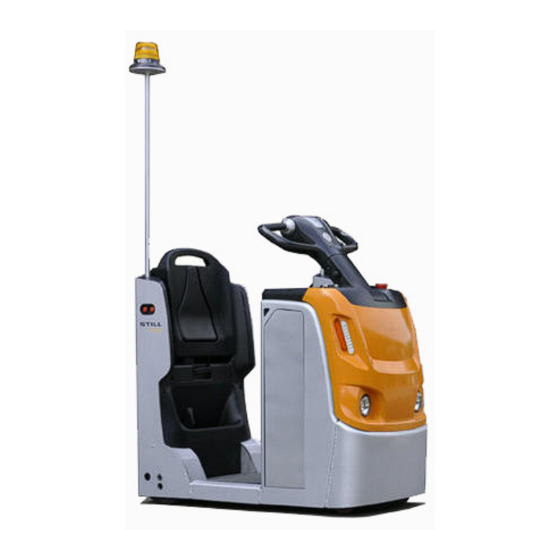
Overviews General view General view Flashing beacon Electromagnetic brake Adjustable auxiliary seat Charger Hook cable Working lights Coupling approach buttons Horn Emergency stop button Fuse & Relay box Hook Indicator lights Load wheels (LTX10 / LTX20), mounted on Key switch main chassis. - Page 43 Overviews General view NOTE The LTX10 / LTX20 tow tractor is equipped with a tow coupling for hitching to a trailer, so there is no tow platform. The LTX -T04 tow tractor has a tow platform and a tow coupling. 1193 801 16 01 EN - 03/2022 - 10...
-
Page 44: Labels
Overviews Labels Labels STILL Logo & truck model label STILL Logo & truck model label STILL Logo sling sticker forbid transport person label key label forbid hook label Importer label (for UK) working shoes label nameplate 1193 801 16 01 EN - 03/2022 - 10... -
Page 45: Identification Plate
Overviews Identification plate Identification plate Nameplate, variant 1 Type Rear axle loading in kg Serial number Manufacturer Year of manufacture Refer to technical data listed in this operat- Unladen mass in kg ing instructions for more detailed information Max. permissible battery weight in kg (for CE label electric trucks only) Towing force... - Page 46 Overviews Identification plate Nameplate, variant 2 Manufacturer the EFTA States and Switzerland UKCA Serial number mark for the United Kingdom market EAC Year of manufacture mark for the Eurasian Economic Union mar- Unladen mass in kg Max. / Min. permissible battery weight in kg Towing force (for electric trucks only) Rated drive power in kW...
-
Page 47: Operating Devices 1193
Overviews Operating devices 1193 Operating devices 1193 Horn button Diagnostic interface STOP button Forward/reverse inching switch Forward/reverse drive direction switch Steel cable Emergency stop switch Tow coupling Tiller adjustment button Auxiliary seat, backrest height adjustment Lighting control switch cable Ticket clip Forward/reverse inching switch Display unit Fold-down auxiliary seat... -
Page 48: Accessory Bar (Optional)
Overviews Accessory bar (optional) Accessory bar (optional) Rear-view mirror Mirror adjuster RF device option or Digicode option Mirror adjuster Additional switch option NOTE For more information, please check the op- tional booklet. The part No. of the booklet is 50988011937. 1193 801 16 01 EN - 03/2022 - 10... -
Page 49: Display Unit
Overviews Display unit CAUTION Beware of pinching fingers when adjusting the tiller. Keep your fingers away from moving parts as shown at the arrow to avoid any risk of injury. WARNING Risk of serious injury and/or serious damage to the equipment. - Page 50 Overviews Display unit Display unit Screen information/indica- Meaning Explanation tion 10 bars remaining:charge level 91–100% 1 bars remaining:1–10% 1 flashing bar remaining:0% Fully charged:100% 10-bar symbol indicating Low charge:10% battery charge Note:in order to protect the Completely discharged:0% battery, the display unit will show 0% remaining power when the battery is left with 20% power...
- Page 51 Overviews Display unit The hour meter commences counting when the vehicle starts working and performs functional operations When the hour meter is run- Indicates the vehicle's work- ning, the hourglass flashes Hour meter ing hours slowly The hour meter displays hours and minutes If the power supply is switched off, the time will be...
-
Page 52: Electronic Key (Option)
Overviews Electronic key (option) Electronic key (option) Switch ON (operating mode) Key fault or incorrect code Switch OFF and awaiting code Time delay of automatic switch-off Programming mode active Operation Enter Status of LEDs Comments ○ red off ● continuous (by de- green (1) (correct PIN) * 1 2 3 4 5 #... -
Page 53: Rf Device (Optional)
Overviews RF device (optional) PROGRAMMING (truck switch OFF only (2)) To reactivate the default Restoring the ini- administrator code tial administrator (00000000), please code contact your agent or nearest dealer. Power switches off auto- ● red flashing ● green matically after 10 mi- Activating the au- flashing (5) (5 seconds nutes (600 seconds by... - Page 54 Overviews RF device (optional) Illustration of reading device variant 924_Lesegerät_01 FleetManagerTM (reading device variant) con- sists of a housing (4) containing an integrated reading device (3). LED 1 (1) and LED 2 (2) serve as a display el- ement.
-
Page 56: Commissioning
Commissioning Commissioning Commissioning advice Check the correct operation of the following devices: We recommend that you avoid excessive use Forward/reverse travel function ● of the vehicle for the first 50 operating hours. Electromagnetic brake function ● During the first few days or the first few oper- Automatic regenerative brake function ●... - Page 57 Before driving Dimensions of the traffic routes and ma- noeuvring areas Turning radius values (Wa) Type LTX10, 1080 mm LTX20 LTX — T04 1660 mm Country-specific regulations must be complied with. Please make sure that there are no overly sharp bends, no excessively steep slopes and that no doors are too narrow or low along the truck's route.
-
Page 58: Designation
Designation Designation Your truck is fitted with special equipment for use in cold stores. It can be used for two oper- ating ranges and carries a cold store label. The cold store equipment for the truck con- sists of using specialised oils (for the gears) suitable for cold stores. -
Page 59: Checks Before Initial Use
Checks before initial use Operating range 1 Permanent use in areas with temperatures of– 5 °C and for short periods of time down to –10 °C. Operating range 2 Alternating use indoors with temperatures down to –32 °C and outside with temperatures up to +25 °C for short periods of time even up to +40 °C. -
Page 60: Daily Checks Before Use
Daily checks before use Automatic regenerative brake function Emergency stop switch function Horn function Operator presence switch Battery lock (only for models equipped with battery lock) Daily checks before use Completion status Inspection item √ Forward/reverse travel function Electromagnetic brake function Automatic regenerative brake function Emergency stop switch function Horn function... -
Page 61: Checking The Working Environment
Checking the working environment Checking the working environment There must be nobody near the tow tractor The places where the tow tractor is used must ● comply with the applicable regulations (condi- The driver must not use a mobile phone, an ●... -
Page 62: Commissioning
Commissioning DANGER DANGER Risk of serious injury and/or serious damage to the Risk of serious injury and/or serious damage to the equipment. equipment. Always keep your hands on the controls, and switch Before setting off in forward or reverse travel, look off the power supply before touching moving parts carefully in the direction of travel to ensure that the and devices. -
Page 63: Emergency Stop Switch
Emergency stop switch – Raise the emergency stop switch (2). – Turn on the power switch (1). – The multifunction display screen (3) will illu- minate; check the status of the vehicle. NOTE Adjust your speed according to the route, the ground conditions and the load.Use the vehi- cle on a flat and hard surface. -
Page 64: Determining The Drive Direction
Determining the drive direction Determining the drive direc- tion – The controls for direction of travel are: Forward travel (1) — towards the tiller ● Reverse travel (2) — towards the tow cou- ● pling Forward/reverse travel – Raise the emergency stop switch, turn on ... -
Page 65: Steering Unit
Steering unit CAUTION Risk of damage to the components. Do not press the switch on one side forward while pressing the switch on the other side backward. Steering unit The steering for the LTX10, LTX20 and LTX-T 04 is controlled using the ergonomic tiller. DANGER Serious risk of personal injury or damage to the equipment. - Page 66 Stand-on/seated driving operation The low step and wide opening on both sides facilitate access to the driver’s work station. The suspended platform, non-slip floor plate and height-adjustable auxiliary seat and tiller provide an extremely comfortable driving ex- perience. Using the auxiliary seat –...
- Page 67 Stand-on/seated driving operation – The auxiliary seat height can be adjusted to provide a suitable driving position. To adjust the auxiliary seat height: Pull out the handle in the direction of the ar- ● row. Adjust the auxiliary seat height by pressing ●...
- Page 68 Stand-on/seated driving operation Adjusting the tiller angle The angle of the tiller can be adjusted to make driving more comfortable. To adjust the tiller angle: Press the button indicated by the arrow ● While holding down the button, adjust the ●...
-
Page 69: Driving On A Slope
Driving on a slope Driving on a slope NOTE We recommend that you do not use the vehi- cle on a slope greater than 5% (with load) or 10% (without load) in order to avoid damaging the motor, brake and/or battery. Exercise extreme caution when using the ve- hicle on a slope: –... - Page 70 Driving on a slope Descending a slope Always travel in forward gear when descend- ing slopes with a load.Unladen vehicles must descend slopes in forward gear(i.e. with the tow coupling facing uphill.) DANGER Risk of death, injury and/or serious damage to the equipment.
-
Page 71: Brake, Horn And Lighting
Brake, horn and lighting NOTE If you need to stop the vehicle more quickly when travelling downhill, press the drive switch into reverse, thereby using reverse braking to increase the braking force. Brake, horn and lighting Electromagnetic safety or parking brake ... -
Page 72: Coupling
Coupling Horn – To sound the horn, press the horn button (6). NOTE Because the vehicle has a mechanical steer- ing unit, it may not be possible to turn corners safely with one hand unless the operator has sufficient arm strength.Therefore, to avoid the above situation when travelling, slow down al- most to a standstill when approaching corners and use the horn to alert pedestrians in blind... -
Page 73: Coupling The Trailer
Coupling the trailer WARNING Risk of serious personal injury and/or equipment damage. Do not operate the tow coupling with the unauthor- ised coupling pin. Coupling the trailer Checking the trailer – Before connecting the trailer to the tow trac- tor, check that the coupling pin hole of the trailer matches the pin hole on the tow trac- tor. - Page 74 Coupling the trailer WARNING Risk of serious injury and/or serious damage to the equipment. During the coupling process, there must be no one between the tow tractor and the trailer. Be sure to use the tow tractor's inching function to complete the coupling operation.
- Page 75 Coupling the trailer – Press the forward or reverse buttons shown in the figure, depending on the required di- rection of travel; the vehicle will start mov- ing. – Release the button to stop the vehicle. NOTE On LTX-T04 models, both sides of the vehicle are equipped with one forward button only.
-
Page 76: Driving The Truck With Cargo
Driving the truck with cargo – Lift the tow tractor's coupling pin. – Uncouple the trailer. Driving the truck with cargo – Always keep the vehicle facing forward when driving; do not travel across a slope or make a U-turn. NOTE Reverse travel must only be used for deposit- ing a load;... - Page 77 Driving the truck with cargo CAUTION Risk of serious injury and/or serious damage to the equipment. Ensure that the load is securely stacked on the trailer with an even weight distribution and that the weight of the tow tractor and trailer is within the tolerance range.
-
Page 78: Transporting The Truck
Transporting the truck CAUTION Risk of damage to the equipment. Park the vehicle on a level surface away from busy traffic routes and protect it from moisture. Transporting the truck Lifting the truck – Lift the truck safely with dedicated lifting ... -
Page 79: Truck Storage
Truck storage Truck storage Measures to be carried out before storing a forklift truck If the tow tractor is taken out of operation for "User Manual" provided by the battery man- over two months, the tow tractor must be ufacturer) parked in a well-ventilated, frost-free, clean –... -
Page 80: Disposal Of Old Trucks
Disposal of old trucks Disposal of old trucks smeared parts, as well as for tyres including The disposal of old trucks is regulated in direc- fire protection measures. Suitable storage tive 2000/53/EC from the European Parlia- tanks for fluids such as fuel, AdBlue® (urea ment and Council. -
Page 81: Maintenance
Maintenance... -
Page 82: General Maintenance Information
Maintenance General maintenance information General maintenance information General The following instructions contain all the infor- Quality and quantity of lubricants and mation required for servicing your truck. Carry other ingredients out the various maintenance tasks in compli- Only lubricants and other ingredients specified ance with the service plan. -
Page 83: Services Not Requiring Special Qualifications
Maintenance General maintenance information Services not requiring special qualifications Simple maintenance operations such as checking the battery electrolyte level can be carried out by persons with no special training. A qualification such as that outlined above is not necessary. Refer to the maintenance sec- tion of this manual for further information. -
Page 84: Recommended Lubricants
Maintenance General maintenance information Recommended lubricants Multi-purpose grease CAUTION Lithium soap grease with EP agents and MoS Damage to equipment if non-recommended lubri- cants are used. 2 KPF 2N - 20 complying with the standard DIN 51825. Only use recommended lubricants. Only the lubri- cants listed below are approved by the manufacturer. -
Page 85: Technical Inspection And Maintenance Characteristics
Maintenance General maintenance information Technical inspection and maintenance characteristics Unit Item/lubricant Quantity/setting/rated value Transmission gear Transmission gear oil 1.3 L Drive wheels Wheel mounting nuts 80 N.m Castor wheels Wheel shaft screw 20 N.m 200 N.m (for tow tractor) / 250 Support wheel Wheel shaft screw N.m (for platform tractor) -
Page 86: Safety Regulations For Maintenance
Maintenance Safety regulations for maintenance Safety regulations for maintenance Safety measures for mainte- nance and repair To prevent accidents during maintenance and repair, perform all necessary safety measures such as: – Ensure that the truck is secured against in- advertent movement or accidental starting (disconnect the battery connector). -
Page 87: Daily Checks Before Starting Work
Maintenance Daily checks before starting work Daily checks before starting work Checking the travel direction control function – Step onto the driver's platform. – Raise the emergency stop switch (1)and start the vehicle. – Carefully operate the forward or reverse travel switch (2). - Page 88 Maintenance Daily checks before starting work Automatic braking – Start the machine moving. – Release the drive switch (1). – Press the "STOP" button (2). – The vehicle will come to a stop. Brake the vehicle by reversing the di- rection of travel –...
-
Page 89: Testing The Steering Unit
Maintenance Daily checks before starting work Parking brake The parking brake is applied automatically if one of the following conditions is met: The driver leaves the operating platform (3) ● The power switch is off (4) ● The travel switch is released and the vehi- ●... - Page 90 Maintenance Daily checks before starting work Emergency stop switch – Push the emergency stop switch (1), the ve- hicle's power supply should shut off; – The electrical control system and motor power supply should shut off; – The electromagnetic brake should brake the vehicle;...
-
Page 91: Checking The Battery Charging Status
Maintenance Daily checks before starting work Checking the battery charging status DANGER Risk of death, injury and/or damage to equipment. The battery must be charged and serviced in accord- ance with the instructions provided with the battery and the battery charger (if an external battery charger is used). -
Page 92: Opening The Battery Hood
Maintenance Daily checks before starting work Opening the battery hood – Stop the vehicle. – Turn off the key switch (1). – Push the emergency stop switch (2). – Pull the battery hood out towards the auxili- ary seat and remove the hood (3) . NOTE It's better to wear protective gloves when op- erate the battery hood. -
Page 93: Checking The Condition Of Cables, Terminals And Battery Connector
Maintenance Daily checks before starting work CAUTION Arcing may occur when the connector makes con- tact, with significant risk of electrical damage. Do not plug in the connector unless the vehicle is powered off.Regularly check the state of the connec- tor contact and replace it immediately if there is arc- ing damage or charring.Strictly adhere to the polarity signs (positive and negative) on the battery polarity. - Page 94 Maintenance Daily checks before starting work NOTE If installing a spare battery, make sure that the specifications of the spare battery (weight, size, voltage, capacity, connector socket) match those of the original battery.Refer to the vehicle rating plate to find out the maximum and minimum weight capacities.
- Page 95 Maintenance Daily checks before starting work – Unplug the battery connector. – Unscrew the screws(1) of the battery fix de- vice on both sides. 1193 801 16 01 EN - 03/2022 - 10...
- Page 96 Maintenance Daily checks before starting work – Lift up the battery fix devices on both sides. – Attach the hoist hook to the battery lifting eyes. – Carefully controlling the hoist, position the battery in the specified location. –...
- Page 97 Maintenance Daily checks before starting work – Unplug the battery connector. – Unscrew the screws(1) of the battery fix de- vice on the battery removed side. 1193 801 16 01 EN - 03/2022 - 10...
- Page 98 Maintenance Daily checks before starting work – Lift up the battery fix devices on the battery removed side. – Unscrew the screws(2) of the side panel. 1193 801 16 01 EN - 03/2022 - 10...
- Page 99 Maintenance Daily checks before starting work – The side panel is inserted on a slot. Re- move the side panel. – Push the moveable support to the side, and keep the moveable support close to the truck. NOTE Make sure that the wheel of the moveable support are locked when using the moveable support to replace the battery.
-
Page 100: Maintenance Plan As Required
If you have taken comprehensive protective measures but water is still seeping in, blow the vehicle dry using compressed air to prevent NOTE rust and short-circuits. - Page 101 Maintenance Maintenance plan as required CAUTION Risk of burns. Brakes, motors, cables, and other electrical compo- nents may reach very high temperatures. Open the electrical compartment cover – Open the battery hood. – Remove the fixing screws from the electri- ...
-
Page 102: Checking The Auxiliary Seat Condition
Maintenance Maintenance plan as required Checking the auxiliary seat con- dition This tow tractor is equipped with a simple aux- iliary seat to support the driver's weight. Inspect the following important points: Check the auxiliary seat height ● Is the height adjustment mechanism stable? ●... - Page 103 Maintenance Maintenance plan as required – Check for blown fuses. – Change any blown fuses. Fuse Specification 125A NOTE We recommend that this work is carried out by a specialised service engineer. 1193 801 16 01 EN - 03/2022 - 10...
-
Page 104: Inspection And Maintenance Overview
Maintenance Inspection and maintenance overview Inspection and maintenance overview 1000 hour service plan Carried At operating hours 1000 Preparations If necessary, clean the truck. Use diagnostic software to read the fault codes. Reset the service interval using the diagnostic software. Lubricate all pivots and lubricate on grease nipple. -
Page 105: 10000 Hour Service Plan
Maintenance Inspection and maintenance overview Carried At operating hours 1000 Test drive the vehicle. 10000 hour service plan Carried At operating hours 10000 20000 30000 Preparations If necessary, clean the truck. Use diagnostic software to read the fault codes. Reset the service interval using the diagnostic software. - Page 106 Maintenance Inspection and maintenance overview Carried At operating hours 10000 20000 30000 Coupling and trailer Check whether the tow coupling is in working order. Check whether the trailer is properly connected. Final inspection Visually inspect the general condition of the undercarriage. Test drive the vehicle.
-
Page 107: Tractor Motor
Maintenance Tractor motor Tractor motor Traction motor:Cleaning the mo- tor housing – Unplug the battery connector. – Open the electrical compartment. – Clean the motor housing with compressed air. – Check the electrical wiring and connectors for signs of overheating. –... -
Page 108: Gearbox
Maintenance Gearbox Gearbox Servicing the reducer Draining the oil NOTE This operation must be carried out by the service centre. 1193 801 16 01 EN - 03/2022 - 10... -
Page 109: Steering/Braking/Wheels
Maintenance Steering/braking/wheels Steering/braking/wheels Steering/wheels/brakes Checking condition and tightness of wheels – Use lifting equipment or a jack to raise the vehicle off the ground, then support the ve- hicle on suitable blocks. – Check that the wheels rotate freely and re- move any coiled wires that may be obstruct- ing them. - Page 110 Maintenance Steering/braking/wheels CAUTION Risk of serious injury and/or serious damage to the equipment. These checks should be performed by an authorised service engineer. Wear protective gloves when re- placing the traction wheel. Adjusting the height of the castor wheels – Use lifting equipment or a jack to raise the vehicle off the ground, then support the ve- hicle on suitable blocks.
- Page 111 Maintenance Steering/braking/wheels – Make sure the standard clearance is 8 mm. – Tighten the screw(2) again. 1193 801 16 01 EN - 03/2022 - 10...
-
Page 112: Checking The Brake Air Gap
Maintenance Steering/braking/wheels Checking the brake air gap IMPORTANT The mechanical braking torque is factory set. – The brake must be checked in the braked position, i.e. with the power supply cut. – Check the air gap on the brake using a set of wheel chocks. -
Page 113: Battery
Maintenance Battery Battery Checking the on-board charger – Connect the cord to the 220 V mains. – Check that the green indicator light on the display is flashing and that the red one is off (charging in progress). – Check that the truck is immobilised (traction is not permitted) as long as it is connected to the 220 V supply. -
Page 114: Removing/Replacing The Battery
Maintenance Battery – Check the condition of the connector con- NOTE tact and keying pins. Contact a service engineer if the density of the – Check the condition of the locking tab on electrolyte in each battery pack is different, or the battery connector. - Page 115 Maintenance Battery CAUTION There is a risk of damaging the machine. Before using the vehicle, make sure that the battery connector is securely connected and locked. CAUTION There is a risk of damaging the machine. Before using the vehicle, make sure that the screws on battery fix device is secured.
- Page 116 Maintenance Battery – Unscrew the screws(1) of the battery fix de- vice on both sides. – Lift up the battery fix devices on both sides. 1193 801 16 01 EN - 03/2022 - 10...
- Page 117 Maintenance Battery – Attach the hoist hook to the battery lifting eyes. – Carefully controlling the hoist, position the battery in the specified location. – To install the replacement battery, perform the above procedure in reverse order. Side access battery: changing the bat- tery using a moveable support –...
- Page 118 Maintenance Battery – Unscrew the screws(1) of the battery fix de- vice on the battery removed side. – Lift up the battery fix devices on the battery removed side. 1193 801 16 01 EN - 03/2022 - 10...
- Page 119 Maintenance Battery – Unscrew the screws(2) of the side panel. – The side panel is inserted on a slot. Re- move the side panel. 1193 801 16 01 EN - 03/2022 - 10...
- Page 120 Maintenance Battery – Push the moveable support to the side, and keep the moveable support close to the truck. NOTE Make sure that the wheel of the moveable support are locked when using the moveable support to replace the battery. Be sure that the moveable support is fixed when replacing the battery.
-
Page 121: Technical Data
Technical data... -
Page 122: Datasheet
Technical data Datasheet Datasheet NOTE 01/2015 Version Characteristics 1.1 Manufacturer Still Still Still 1.2 Model designation LTX10 LTX20 LTX-T 04 1.3 Power unit Battery Battery Battery 1.4 Operation Stand-on Stand-on Stand-on 1.5 Load capacity kg 1000 2000 400/1000 1.6 Rated drawbar pull N 190 1.7 Wheelbase... - Page 123 Technical data Datasheet Weight Service weight kg 620 Axel load without load, front (drive)// kg 350 / 280 350 / 280 460 / 270 rear (load) Wheels Tyres, front (drive)/rear (load) C+PU/C C+PU/C C+PU/C C=cushion rubber, P=polyurethane Tyre size, front (drive) wheel mm Ø230X75 Ø230X75 Ø230X75...
- Page 124 Technical data Datasheet Dimensions Ground clearance, center of wheel- m2 mm 40/80 40/80 base Turning radius Wa mm 1080 1080 1660 Performances 5.1 Travel speed, with/without load 10/10 5.2 Drawbar pull (60 minutes rating) N 190 Maximum drawbar pull (5 minutes N 1760 1760 1760...
- Page 125 Technical data Datasheet 1) Including item 6.5 battery weight. 2) ± 5mm 3) >=95% 4) <=105% 5) >=100% 6) ± 5% 7) ± 4mm 8) The number of laps around the standard testing track in one hour. 9) With single position hook. 10) Platform load capacity is 400 kg and hook load capacity is 1000 kg.
- Page 126 Technical data Datasheet 1193 801 16 01 EN - 03/2022 - 10...
- Page 127 Index Cross references..... 7 UMBERS AND YMBOLS 10000 hour service plan....1000 hour service plan.
- Page 128 Index Measures to be carried out before storing a Safety devices forklift truck..... . . Misuse......Measuring battery insulation resistance.
- Page 130 STILL GmbH 1193 801 16 01 EN - 03/2022 - 10...
Need help?
Do you have a question about the LTX Series and is the answer not in the manual?
Questions and answers