Still LTX20 Original Instructions Manual
Hide thumbs
Also See for LTX20:
- Original instructions manual (114 pages) ,
- Original instructions manual (130 pages)
Table of Contents
Advertisement
Quick Links
Advertisement
Table of Contents

Related Manuals for Still LTX20


Summary of Contents for Still LTX20
- Page 1 Original instructions LTX20, LTX-T04 Tractor 0611 0612 11938011500 EN - 05/2015...
-
Page 3: Table Of Contents
Table of contents Foreword Your industrial truck ........... 2 General . - Page 4 Table of contents Safety tests ............23 Regular safety inspection of the truck .
- Page 5 Table of contents Battery connection cables ..........30 Overviews General view .
- Page 6 Table of contents Services not requiring special qualifications ....... . 63 Ordering spare parts and wear parts .
- Page 7 Table of contents Technical data Datasheet ............94 11938011500 [EN]...
-
Page 9: Foreword
Foreword... -
Page 10: Your Industrial Truck
Foreword Your industrial truck Your industrial truck General The truck described in these operating instruc- tions corresponds to the applicable standards and safety regulations. If the truck is to be operated on public roads, it must conform to the existing national regula- tions for the country in which it is being used. -
Page 11: Legal Requirements For Placing On The Market
5 Loyang Way, 508720, Singapore We declare that the machine Industrial truck Tractor LTX20, LTX-T04 Model complies with the most recent version of machinery directive 2006/42/EC. Personnel authorised to compile the technical documents: Name: Christian Baerwolff Address: Berzeliusstrasse 10, 22113... -
Page 12: Information About Documentation
Foreword Information about documentation also be handed over to the new owner if the truck is sold on. Information about documentation Documentation scope • Operating instructions • Operating instructions for attachment parts (special equipment) • Spare parts list • VDMA rules for the proper use of industrial trucks These operating instructions describe all mea- sures necessary for the safe operation and... - Page 13 Foreword Information about documentation The operating company (see ⇒ Chapter "Def- inition of terms used for responsible per- sons", P. 18) must ensure that all operators have received, read and understood these instructions. Thank you for reading and complying with these operating instructions.
-
Page 14: Date Of Edition And Latest Update Of This Manual
Foreword Information about documentation Date of edition and latest update of this manual The publication date of these operating instructions is printed on the cover sheet. The manufacturer makes continuous efforts to improve its industrial trucks, and therefore reserves the right to implement changes and to accept no claims concerning the information provided in this manual. -
Page 15: Explanation Of Symbols Used
Foreword Information about documentation Explanation of symbols used DANGER Compulsory procedure that must be followed to avoid danger to life or physical harm. WARNING Compulsory procedure that must followed to avoid injury. CAUTION Compulsory procedure that must be followed to avoid material damage and/or destruction. -
Page 16: Definition Of Directions
Foreword Information about documentation Definition of directions The directions front (1), rear (3), right (2) and left (4) are seen from the position of the operator; the load is at the rear. Illustrations At many points in this documentation the (mostly sequential) operation of certain func- tions or operating procedures is explained. -
Page 17: Environmental Considerations
Foreword Environmental considerations Environmental considerations Packaging During delivery of the truck, certain parts are packaged to provide protection during transport. This packaging must be removed completely prior to initial start-up. ENVIRONMENT NOTE The packaging material must be disposed of properly after delivery of the truck. Disposal of components and batteries The truck is composed of different materials. - Page 18 Foreword Environmental considerations 11938011500 [EN]...
-
Page 19: Introduction
Introduction... -
Page 20: Technical Description
The latter is applied automatically in the proach control for coupling to a trailer. following situations: LTX20 travels a distance of 0.3 m each time • the driver leaves the driving platform. the button (forward or reverse) is held down. -
Page 21: Use Of The Truck
- an ignition key or digicode allowing the truck to be used by authorised personnel without an Coupling options: ignition key; single position of LTX20:113 mm - an emergency stop button; single position of LTX-T04:173 mm - a diagnostic connector;... -
Page 22: Unauthorised Use
Introduction Use of the truck tions, the approval of the manufacturer and, if applicable, the relevant regulatory authorities must be obtained beforehand to prevent haz- ards. The maximum load is specified on the capacity rating plate (load diagram) and must not be exceeded;... -
Page 23: Residual Risks
Introduction Residual risks If your truck is to be used in a refrigerated stor- age area, it must be configured accordingly and, if necessary, approved for that environ- ment (see ⇒ Chapter "Designation", P. 5-42). The operator (see ⇒ Chapter "Definition of terms used for responsible persons", P. -
Page 24: Special Risks Associated With Using The Truck And Attachments
Introduction Residual risks according to its intended purpose. These standards only take into account the static and dynamic tipping forces that can arise during specified use in accordance with the operating rules and intended purpose. The risk of exceeding the moment of tilt that arises from improper use or incorrect operation cannot be excluded in extreme cases, and will impact stability. -
Page 25: Safety
Safety... -
Page 26: Definition Of Terms Used For Responsible Persons
Safety Definition of terms used for responsible persons Definition of terms used for responsible persons Operating company The operating company is the natural or legal person or group who operates the truck or on whose authority the truck is used. The operating company must ensure that the truck is only used for its proper purpose and in compliance with the safety regulations set out... -
Page 27: Expert
Safety Definition of terms used for responsible persons regarding the industrial truck to be tested and the risk being assessed Expert An expert is considered to be someone whose technical training and experience have en- abled them to develop appropriate knowledge of industrial trucks and who is sufficiently fa- miliar with the applicable national health and safety regulations, directives and generally... - Page 28 Safety Definition of terms used for responsible persons and safety gloves) suited to the operating con- ditions, the job and the load. The driver must wear safety footwear for driving and braking in complete safety. The drive must be familiar with the operating instructions, which must remain accessible at all times.
-
Page 29: Basic Principles For Safe Operation
STILL. CAUTION Installation and/or use of such products may there- fore have a negative impact on the design features of the truck and thus impair active and/or passive driving safety. -
Page 30: Medical Equipment
Safety Basic principles for safe operation You should therefore contact the manufac- turer before carrying out any modification. No modification that may affect stability is permit- ted without the manufacturer’s authorisation. Any constructional modification or transfor- mation of your truck is forbidden without prior written permission from the manufacturer. -
Page 31: Safety Tests
Safety Safety tests Safety tests Regular safety inspection of the truck Safety inspection based on time and extraordinary incidents The operating company must ensure that the truck is checked by a specialist at least once a year or after particular incidents. As part of this inspection, a complete check of the technical condition of the truck must be performed with regard to accident safety. -
Page 32: Safety Regulations For Handling Consumables
Safety Safety regulations for handling consumables Measuring battery insulation resistance NOTE Nominal battery voltage < test voltage < 500V. – Measure insulation resistance using a suitable meter. The insulation resistance is sufficient when it has a nominal value of at least 1000 Ohms/V against the chassis. -
Page 33: Oils
Safety Safety regulations for handling consumables Oils DANGER Oils are flammable! – Follow the statutory regulations. – Do not allow oils to come into contact with hot engine parts. – No smoking, fires or naked flames! DANGER Oils are toxic! –... -
Page 34: Hydraulic Fluid
Safety Safety regulations for handling consumables ENVIRONMENT NOTE Oil is a water-polluting substance! Always store oil in containers that comply • with the applicable regulations. Avoid spilling oils. • Spilt oil should be removed immediately • with oil-binding agents and disposed of according to the regulations. -
Page 35: Battery Acid
Safety Safety regulations for handling consumables ENVIRONMENT NOTE Hydraulic fluid is a water-polluting substance. Always store hydraulic fluid in containers • that comply with regulations Avoid spills • Spilt hydraulic fluid should be removed • immediately with oil-binding agents and disposed of according to the regulations Dispose of old hydraulic fluid according to •... -
Page 36: Disposal Of Consumables
Safety Safety regulations for handling consumables Disposal of consumables ENVIRONMENT NOTE Materials that accumulate during repair, maintenance and cleaning must be collected properly and disposed of in accordance with the national regulations for the country in which the truck is being used. Work must only be carried out in areas designated for the purpose. - Page 37 Safety Safety regulations for handling consumables Vibrations Machine vibrations were measured using an identical machine , in accordance with Standard CEN EN 13059 "Test methods for measuring vibration by industrial trucks". Trials have shown that the amount of hand- arm vibration when using the steering wheel and controls is less than 2.5 m/s for industrial trucks.
-
Page 38: Safety Devices
Safety Safety devices Safety devices Damage, defects and misuse of safety devices The driver must report any damage or other defects to the truck or attachment immediately to the supervisory personnel. Trucks and attachments that are not functional or safe may not be used until they have been properly repaired. -
Page 39: Overviews
Overviews... -
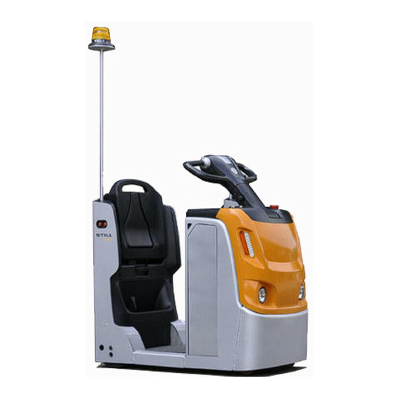
Page 40: General View
Overviews General view General view Flashing beacon Hook Adjustable seat Load wheels Hook cable Operator platform Coupling approach buttons Buttery Emergency stop button Stabiliser wheels 11938011500 [EN]... -
Page 41: Labels
Overviews Labels Drive wheel Key switch Electrical motor Indicator Electromagnetic brake Diagnostic connector Charger Control panel Working lights Steering handlebar Horn Horn button Fuse & Relay box Direction switch Indicator lights Stop button Labels company label&truck model label company label for OM brand company label identification plate forbid transport person label... -
Page 42: Identification Plate
Overviews Identification plate Identification plate Identification plate for LTX20 Type Rear axle loading in kg Serial number Manufacturer Year of manufacture Refer to technical data listed in this operating Unladen mass in kg instructions for more detailed information Max. permissible battery weight in kg (for... - Page 43 Overviews Identification plate Identification plate for LTX-T04 Type Ballast weight in kg (for electric trucks only) Serial number Manufacturer Year of manufacture Refer to technical data listed in this operating Unladen mass in kg instructions for more detailed information Max. permissible battery weight in kg (for CE label electric trucks only) Rated drive power in kW...
-
Page 44: Operating Devices 1193
Overviews Operating devices 1193 Operating devices 1193 Horn button Diagnostic interface STOP button Forward/reverse inching switch Forward/reverse drive direction switch Steel cable Emergency stop switch Tow coupling Tiller adjustment button Seat, backrest height adjustment cable Lighting control switch Forward/reverse inching switch Ticket clip Fold-down seat Display unit... - Page 45 Overviews Display unit • indicates fault messages by means of flashing indicator light or symbols • displays battery charge status • equipped with backlight The controller transmits battery power, hours, fault codes and other information to the display unit over the CAN-BUS network. Display unit Screen information/indica- Meaning...
- Page 46 Overviews Display unit Off:indicates that the vehicle is switched off Yellow indicator light Solid light:indicates that the vehicle is switched on Fault codes help service department engineers to Error codes correctly diagnose faults Failure or brake worn (air Cannot operate vehicle gap) The hour meter com- mences counting when the...
-
Page 48: Commissioning
Commissioning Commissioning Commissioning advice Check the correct operation of the following devices: We recommend that you avoid excessive use • Forward/reverse travel function of the vehicle for the first 50 operating hours. • Electromagnetic brake function During the first few days or the first few •... - Page 49 Before driving Danger area The hazard area is the area in which people are in danger from the tow truck movements, from its work equipment and from its trailers or from the load. The areas in which a load could fall or work equipment could lower or fall are also part of the hazard area.
-
Page 50: Designation
Designation Hazards Hazards on the traffic routes must be signalled by current road signs or possibly by additional warning notices. Designation Your truck is fitted with special equipment for use in cold stores. It can be used for two operating ranges and carries a cold store label. - Page 51 Designation Prior to start-up CAUTION The truck must be dry and at operating temperature before being used in the cold store. – Drive the truck for approximately 5 minutes and operate the brakes several times to ensure the truck operates safely. Operating range 1 Permanent use in areas with temperatures of–5 °C and for short periods of time down to...
-
Page 52: Checks Before Initial Use
Checks before initial use Checks before initial use Completion status Inspection item √ Dashboard settings Forward/reverse travel function Electromagnetic brake function Automatic regenerative brake function Emergency stop switch function Horn function Operator presence switch Battery lock (only for models equipped with battery lock) Daily checks before use Completion status Inspection item... -
Page 53: Checking The Working Environment
Operating instructions The LTX20 and LTX-T04 are for indoor use NOTE in non-hazardous atmospheres; the ambient temperature must be between -10°C and The platform of LTX-T04 can load 400kg +40°C and the air humidity less than 95%. -
Page 54: Commissioning
Commissioning DANGER DANGER Risk of serious injury and/or serious damage to the Risk of serious injury and/or serious damage to the equipment. equipment. Always keep your hands on the controls, and switch Before setting off in forward or reverse travel, look off the power supply before touching moving parts carefully in the direction of travel to ensure that the and devices. -
Page 55: Emergency Stop Switch
Emergency stop switch – Raise the emergency stop switch (2). – Turn on the power switch (1). – The multifunction display screen (3) will illuminate; check the status of the vehicle. NOTE Adjust your speed according to the route, the ground conditions and the load.Use the vehicle on a flat and hard surface. -
Page 56: Forward/Reverse Travel
Forward/reverse travel Forward/reverse travel – Raise the emergency stop switch, turn on the power switch. Forward travel – Slowly press the drive switch forward with your thumb. – The vehicle will move forward in the same direction as the direction of the drive switch. CAUTION Risk of damage to the components. -
Page 57: Stand-On/Seated Driving Operation
Stand-on/seated driving operation Steering directions in forward travel – Turn the tiller clockwise — the truck should turn to the right. – Turn the tiller anti-clockwise — the truck should turn to the left. Stand-on/seated driving operation CAUTION The driver must only perform driving manoeuvres after making the following adjustments: –... - Page 58 Stand-on/seated driving operation – The auxiliary seat height can be adjusted to provide a suitable driving position. To adjust the auxiliary seat height: • Pull out the handle in the direction of the arrow. • Adjust the auxiliary seat height by pressing down on the auxiliary seat while standing beside the vehicle.
- Page 59 Stand-on/seated driving operation – Sliding rail for raising and lowering the auxiliary seat. WARNING Risk of hurting figures. Be careful when adjusting the auxiliary seat height, don’t put the figure into the rail of the auxiliary seat. Adjusting the tiller angle The angle of the tiller can be adjusted to make driving more comfortable.
-
Page 60: Driving On A Slope
Driving on a slope Driving on a slope NOTE We recommend that you do not use the vehicle on a slope greater than 5% (with load) or 10% (without load) in order to avoid damaging the motor, brake and/or battery. Exercise extreme caution when using the vehicle on a slope: –... - Page 61 Driving on a slope CAUTION Driving on slopes greater than 10% is prohibited due to limited braking capacity. For safety reasons if the maximum speed is excee- ded, e.g. when operating on a slope over a long distance or on a very steep slope, the electroma- gnetic brake will be activated automatically.
-
Page 62: Brake, Horn And Lighting
Brake, horn and lighting Brake, horn and lighting Electromagnetic safety or parking brake system The electromagnetic brake is applied automa- tically in the following circumstances: • When the drive direction switch (1) fails • When the operator leaves the driver’s platform (3) •... -
Page 63: Coupling
Coupling Coupling There are two types of the hook: • Use the cable to control the hook. It can be controlled by the driver when stand in the driver’s platform. • Use the rigid pole to control the hook. – To release the coupling, manually pull the cable or the rigid pole upwards. - Page 64 Coupling the trailer CAUTION Risk of damage to the equipment. Before coupling the trailer to the tow tractor, check that the coupling pin hole of the trailer matches the coupling pin hole on the tow tractor. WARNING Risk of serious injury and/or serious damage to the equipment.
- Page 65 Coupling the trailer – Press the forward or reverse buttons shown in the figure, depending on the required direction of travel; the vehicle will start moving. – Release the button to stop the vehicle. NOTE On LTX-T04 models, both sides of the vehicle are equipped with one forward button only.
-
Page 66: Driving The Truck With Cargo
Driving the truck with cargo – Lift the tow tractor’s coupling pin. – Uncouple the trailer. Driving the truck with cargo – Always keep the vehicle facing forward when driving; do not travel across a slope or make a U-turn. NOTE Reverse travel must only be used for depo- siting a load;... - Page 67 Driving the truck with cargo CAUTION Risk of serious injury and/or serious damage to the equipment. Ensure that the load is securely stacked on the trailer with an even weight distribution and that the weight of the tow tractor and trailer is within the tolerance range.
- Page 68 Driving the truck with cargo 11938011500 [EN]...
-
Page 69: Maintenance
Maintenance... -
Page 70: General Maintenance Information
Maintenance General maintenance information General maintenance information General Quality and quantity of lubricants and The following instructions contain all the information required for servicing your truck. other ingredients Carry out the various maintenance tasks Only lubricants and other ingredients specified in compliance with the service plan. -
Page 71: Services Not Requiring Special Qualifications
Maintenance General maintenance information Services not requiring special qualifications Simple maintenance operations such as checking the hydraulic fluid level or checking the battery electrolyte level can be carried out by persons with no special training. A qualification such as that outlined above is not necessary. -
Page 72: Recommended Lubricants
Maintenance General maintenance information Recommended lubricants CAUTION CAUTION Damage to equipment if non-recommended lubri- Follow the maintenance and safety instructions. cants are used. Multi-purpose grease Only use recommended lubricants. Only the lu- bricants listed below are approved by the manu- Lithium soap grease with EP agents and MoS facturer. -
Page 73: Safety Regulations For Maintenance
Maintenance Safety regulations for maintenance Safety regulations for maintenance Safety measures for maintenance and repair To prevent accidents during maintenance and repair, perform all necessary safety measures such as: – Ensure that the truck is secured against in- advertent movement or accidental starting (disconnect the battery connector). -
Page 74: Daily Checks Before Starting Work
Maintenance Daily checks before starting work Daily checks before starting work Checking the travel direction control function – Step onto the driver’s platform. – Raise the emergency stop switch (1)and start the vehicle. – Carefully operate the forward or reverse travel switch (2). - Page 75 Maintenance Daily checks before starting work Brake the vehicle by reversing the direction of travel – Start the machine moving. – Push the drive direction switch (1) in the opposite direction to the direction of travel until the vehicle comes to a stop. –...
-
Page 76: Testing The Steering Unit
Maintenance Daily checks before starting work Testing the steering unit – Drive the vehicle forwards slowly. – Turn tiller clockwise — vehicle should turn to the right. – Turn tiller anti-clockwise — vehicle should turn to the left. – Turn tiller to middle position — vehicle should travel in a straight line. -
Page 77: Checking The Battery Charging Status
Maintenance Daily checks before starting work Horn – Push the horn switch (6). – The horn should sound. Checking the battery charging status DANGER Risk of death, injury and/or damage to equipment. The battery must be charged and serviced in accordance with the instructions provided with the battery and the battery charger (if an external battery charger is used). -
Page 78: Opening The Battery Hood
Maintenance Daily checks before starting work – Before replacing the battery, check whether the battery is able to charge properly. – Plugging in the battery connector. – Pull up the emergency stop switch (2) to power on the vehicle. – Check the battery charge status on the multifunction display (3). -
Page 79: Plugging In/Unplugging The Battery Connector
Maintenance Daily checks before starting work Plugging in/unplugging the battery connector Unplugging the connector – Stop the vehicle and turn off the power switch. – Open the battery hood. – The battery connector is located at the side of the battery. –... -
Page 80: Checking The Condition Of Cables, Terminals And Battery Connector
Maintenance Daily checks before starting work Checking the condition of cables, terminals and battery connector – Make sure that the cable insulation is not damaged and that the connector shows no signs of heating. – Check that the positive and negative output line terminals are not sulphated (presence of white salt). - Page 81 Maintenance Daily checks before starting work CAUTION Beware of pinching your fingers when removing and fitting the battery. Keep your fingers away from moving parts to avoid any risk of trapping. CAUTION There is a risk of damaging the machine. Before using the vehicle, make sure that the battery connector is securely connected and locked.
- Page 82 Maintenance Daily checks before starting work – Lift up the battery fix devices on both sides. – Attach the hoist hook to the battery lifting eyes. – Carefully controlling the hoist, position the battery in the specified location. – To install the replacement battery, perform the above procedure in reverse order.
- Page 83 Maintenance Daily checks before starting work – Unscrew the screws(1) of the battery fix device on the battery removed side. – Lift up the battery fix devices on the battery removed side. – Unscrew the screws(2) of the side panel. –...
-
Page 84: Maintenance Plan As Required
NOTE If you have taken comprehensive protective measures but water is still seeping in, blow the Before cleaning the tow tractor, disconnect vehicle dry using compressed air to prevent its power supply.Steam cleaning equipment rust and short-circuits. -
Page 85: Accessing The Electrical Compartment
Maintenance Maintenance plan as required – If sulphate build-up is heavy, you will need ENVIRONMENT NOTE to take out the battery, jet wash it and clean Do not pour acidic cleaning water down the the frame. drain.For more information, refer to the battery usage instructions. -
Page 86: Checking The Seat Condition
Maintenance Maintenance plan as required – Remove the fixing screws from the electrical compartment cover. NOTE Follow the disassembly steps in reverse order to refit the electrical compartment cover. Checking the seat condition This tow tractor is equipped with a simple seat to support the driver’s weight. -
Page 87: Check Fuses
Maintenance Inspection and maintenance overview CAUTION Risk of serious accidents. Do not drive the machine if the tiller is faulty. Check fuses – Remove the front cover of the tow tractor. – Check for blown fuses. – Change any blown fuses. Specification Fuse 125A... -
Page 88: 10000 Hour Service Plan
Maintenance Inspection and maintenance overview Carried At operating hours 1000 Check that the nuts are tightened. Check the parking brake clearance. Check the castor wheels clearance when stationary. Electrical equipment Disconnect power, clean circuit. Check the contacts and terminals of the contactors. Switch off the LAC controller and clean it. - Page 89 Maintenance Inspection and maintenance overview Carried At operating hours 10000 20000 30000 Traction motor Clean the motor housing. Transmission Change the reducer gear oil. Wheels/brake system Check the wear on the tyre tread of the wheels. Check that the nuts are tightened. Check the parking brake clearance.
-
Page 90: Tractor Motor
Maintenance Tractor motor Tractor motor Traction motor:Cleaning the motor housing – Unplug the battery connector. – Open the electrical compartment. – Clean the motor housing with compressed air. – Check the electrical wiring and connectors for signs of overheating. – Check that the connections are tight. 11938011500 [EN]... -
Page 91: Gearbox
Maintenance Gearbox Gearbox Servicing the reducer Draining the oil NOTE This operation must be carried out by the service centre. Steering/braking/wheels Steering/wheels/brakes Checking condition and tightness of wheels – Use lifting equipment or a jack to raise the vehicle off the ground, then support the vehicle on suitable blocks. - Page 92 Maintenance Steering/braking/wheels Checking that the wheels are tightened – Use lifting equipment or a jack to raise the vehicle off the ground, then support the vehicle on suitable blocks. – Remove the front cover. – Check the tightness of the nuts on the drive wheel, recommended torque setting: 80 N.m.
-
Page 93: Checking The Brake Air Gap
Maintenance Battery Checking the brake air gap IMPORTANT The mechanical braking torque is factory set. – The brake must be checked in the braked position, i.e. with the power supply cut. – Check the air gap on the brake using a set of wheel chocks. -
Page 94: Battery Maintenance
Maintenance Battery Battery maintenance The following steps relate to lead-acid batter- ies with electrolyte. CAUTION Risk of serious injury and/or serious damage to the equipment. Avoid contact with the electrolyte.Avoid causing a short circuit.Refer to the recommendations in the daily checks section.Wear protective gloves and goggles when working on the battery.In case of contact with eyes or skin, rinse immediately with plenty of clean water, then seek medical advice if... - Page 95 Maintenance Battery Measuring the electrolyte density Measuring the density gives an accurate indication of the charging status of each cell (only in an open lead-acid battery).This measurement can be taken before or after charging. • The minimum density when the battery is 80% discharged is 1.14.
-
Page 96: Removing/Replacing The Battery
Maintenance Battery Removing/replacing the battery NOTE NOTE When handling batteries, make sure that all lifting equipment used (crane, hoist, slings, hooks, vehicles, handling devices) is sufficient for the weight of the battery. NOTE If installing a spare battery, make sure that the specifications of the spare battery (weight, size, voltage, capacity, connector socket) match those of the original battery.Refer to the... - Page 97 Maintenance Battery – Unplug the battery connector. – Unscrew the screws(1) of the battery fix device on both sides. – Lift up the battery fix devices on both sides. 11938011500 [EN]...
- Page 98 Maintenance Battery – Attach the hoist hook to the battery lifting eyes. – Carefully controlling the hoist, position the battery in the specified location. – To install the replacement battery, perform the above procedure in reverse order. Side access battery: changing the battery using a moveable support –...
- Page 99 Maintenance Battery – Lift up the battery fix devices on the battery removed side. – Unscrew the screws(2) of the side panel. – The side panel is inserted on a slot. Remove the side panel. 11938011500 [EN]...
- Page 100 Maintenance Battery – Push the moveable support to the side, and keep the moveable support close to the truck. NOTE Make sure that the wheel of the moveable support are locked when using the moveable support to replace the battery. Be sure that the moveable support is fixed when replacing the battery.
- Page 101 Technical data...
- Page 102 Technical data Datasheet Datasheet NOTE 01/2015 Version Characteristics 1.1 Manufacturer Still Still 1.2 Model designation LTX20 LTX-T 04 Battery Battery 1.3 Power unit Stand- Stand- 1.4 Operation ing/Seated ing/Seated 1.5 Load capacity kg 2000 400/1000 1.6 Rated drawbar pull N 400...
- Page 103 Technical data Datasheet Wheels 3.3 Tyre size, rear (load) wheel mm 2 X Ø250X80 2 X Ø250X80 3.4 Auxiliary wheels(dimensions) mm 2 X Ø100X40 2 X Ø100X40 Wheels, number front (drive)/rear (load) 1x+2/2 1x+2/2 (x=driven) 3.6 Track width, front (drive) mm 414 3.7 Track width, rear (load) mm 480...
- Page 104 Technical data Datasheet Drive 6.4 Battery voltage/rated capacity (5h) V/Ah 24/200 24/200 6.5 Battery weight (±5%) kg 185 6.6 Energy comsumption acc. to VDI cycle kWh/h 1.21 (62 cycles) 1.35 (59 cycles) Others 8.1 Type of drive control 8.2 Noise level at operator’s ear dB 75 Vibration to the operator, LTX 20 / LTX - 1.28/1.33...
- Page 105 Index NUMBERS AND SYMBOLS Coupling ......55 Coupling the trailer ....55 1000 hour service plan .
- Page 106 Index Illustrations ..... . . 8 Removing/replacing the battery ..72, 88 Insurance cover on company premises . . 21 Residual dangers, residual risks .
- Page 108 STILL GmbH Berzeliusstrasse 10 D-22113 Hamburg Ident no. 11938011500 EN...
Need help?
Do you have a question about the LTX20 and is the answer not in the manual?
Questions and answers