
Related Manuals for Still CX-T-40


Summary of Contents for Still CX-T-40
- Page 1 Original instructions Electric tow tractor CX-T-40 1066 51048070007 EN - 00-10/2013...
-
Page 3: Table Of Contents
Table of contents Foreword Your industrial truck ........... 2 General . - Page 4 Table of contents Medical equipment ..........27 Safety tests .
- Page 5 Table of contents Starting with FleetManager (optional) ........56 Hour meter .
- Page 6 Table of contents Handling the battery ..........90 Preparation .
- Page 7 Table of contents Maintenance every 500 hours ......... . . 115 Other tasks .
-
Page 9: Foreword
Foreword... -
Page 10: Your Industrial Truck
Foreword Your industrial truck Your industrial truck General The truck described in these operating instruc- tions corresponds to the applicable standards and safety regulations. If the truck is to be operated on public roads, it must conform to the existing national regula- tions for the country in which it is being used. -
Page 11: Ec Declaration Of Conformity In Accordance With Machinery Directive
Foreword Your industrial truck EC declaration of conformity in accordance with Machinery Directive Declaration STILL GmbH Berzeliusstraße 10 D-22113 Hamburg Germany We declare that the according to these operating instructions Industrial truck according to these operating instructions Model conforms to the latest version of the Machinery Directive 2006/42/EC. -
Page 12: Information About Documentation
Foreword Information about documentation Information about documentation Documentation scope • Operating instructions • Operating instructions for attachment parts (special equipment) • Spare parts list • VDMA rules for the proper use of industrial trucks These operating instructions describe all mea- sures necessary for the safe operation and proper maintenance of the truck in all possible variants at the time of printing. - Page 13 Foreword Information about documentation Thank you for reading and complying with these operating instructions. If you have any questions or suggestions for improvements, or if you have found any faults, please contact your service centre. 51048070007 [EN]...
-
Page 14: Date Of Edition And Latest Update Of This Manual
The issue date of these instructions can be found on the title page. STILL is constantly working to improve its trucks. These instructions are subject to change and claims cannot be validly asserted against the statements and images found in these operating instructions. -
Page 15: Explanation Of Symbols Used
Foreword Information about documentation Explanation of symbols used DANGER Compulsory procedure that must be followed to avoid danger to life or physical harm. WARNING Compulsory procedure that must followed to avoid injury. CAUTION Compulsory procedure that must be followed to avoid material damage and/or destruction. -
Page 16: Defining Directions
Foreword Information about documentation Defining directions Terms used in the text: forward travel (1), reverse travel (3), to the right (2) and to the left (4) refer to the installation position of the components in relation to the driver’s compartment, with the load positioned at the rear. -
Page 17: Environmental Considerations
Foreword Environmental considerations Environmental considerations Packaging During delivery of the truck, certain parts are packaged to provide protection during transport. This packaging must be removed completely prior to initial start-up. ENVIRONMENT NOTE The packaging material must be disposed of properly after delivery of the truck. Disposal of components and batteries The truck is composed of different materials. - Page 18 Foreword Environmental considerations 51048070007 [EN]...
-
Page 19: Introduction
Introduction... -
Page 20: Use Of The Tow Tractor
Introduction Use of the tow tractor Use of the tow tractor Intended use of the trucks CAUTION This machine is designed to tow industrial trailers and for the storage of loads packed on pallets or in industrial containers designed for this purpose. The dimensions and capacity of the trailers, pallets or containers must be adapted to the load being transported and must ensure stability. -
Page 21: Place Of Use
Introduction Use of the tow tractor WARNING There is a risk of accident! Passengers are not allowed. The forklift truck may not be operated in areas where is a risk of fire, explosion or corrosion, or areas that are particularly dusty. Stacking or unstacking is not permissible on inclined surfaces or ramps. -
Page 22: Residual Risks
Introduction Residual risks Residual risks Residual dangers, residual risks Despite careful working and compliance with standards and regulations, the occurrence of other risks when using the truck cannot be entirely excluded. The truck and all other system components comply with current safety requirements. Nevertheless, even when the truck is used for its proper purpose and all instructions are followed, some residual risk cannot be... -
Page 23: Special Risks Associated With Using The Truck And Attachments
Introduction Residual risks The manufacturer is not held responsible for accidents involving the truck caused by the failure of the operating company to comply with these regulations either intentionally or carelessly. Stability The stability of the truck has been tested to the latest technological standards and is guaranteed if the truck is used properly and according to its intended purpose. -
Page 24: Overview Of Hazards And Countermeasures
Introduction Residual risks Overview of hazards and counter- measures NOTE This table is intended to help evaluate the hazards in your facility and applies to all drive types. It does not claim to be complete. NOTE Observe the national regulations for your country! Hazard Measure... - Page 25 Introduction Residual risks Hazard Measure Check note Notes √ actioned - not applicable Impermissible usage Issuing of operating BetrSichVO (improper usage) instructions (Workplace Safety Ordinance) and ArbSchG (Health and Safety at Work Act) Written notice of BetrSichVO instruction to driver (Workplace Safety Ordinance) and ArbSchG (Health and...
-
Page 26: Hazards To Employees
Introduction Residual risks Hazard Measure Check note Notes √ actioned - not applicable With driverless transport systems Roadway quality Clean/clear driveways BetrSichVO inadequate (Workplace Safety Ordinance) Load carrier Reattach load to pallet BetrSichVO incorrect/slipped (Workplace Safety Ordinance) Drive behaviour Employee training BetrSichVO unpredictable (Workplace Safety... - Page 27 Introduction Residual risks The results must be documented (§ 6 Arb- SchG). In the case of truck deployment involv- ing similar hazard situations it is permitted to summarise the results. This overview (see ⇒ Chapter "Overview of hazards and coun- termeasures", P.
- Page 28 Introduction Residual risks 51048070007 [EN]...
-
Page 29: Safety
Safety... -
Page 30: Definition Of Terms Used For Responsible Persons
Safety Definition of terms used for responsible persons Definition of terms used for responsible persons Operating company The operating company is the natural or legal person or group who operates the truck or on whose authority the truck is used. The operating company must ensure that the truck is only used for its proper purpose and in compliance with the safety regulations set out... -
Page 31: Driver
Safety Definition of terms used for responsible persons truck to be tested and the risk being as- sessed. Driver This truck may only be driven by suitable per- sons who are at least 18 years of age, have been trained in driving, have demonstrated their skills in driving and handling loads to the operating company or an authorised rep- resentative, and have been specifically in-... - Page 32 Safety Definition of terms used for responsible persons DANGER The use of drugs, alcohol or medications that have an effect on reactions impair a person’s ability to drive the truck! Individuals under the influence of the aforementio- ned substances are not permitted to perform any work on or with an industrial truck.
-
Page 33: Basic Principles For Safe Operation
STILL. CAUTION Installation and/or use of such products may there- fore have a negative impact on the design features of the truck and thus impair active and/or passive driving safety. - Page 34 Safety Basic principles for safe operation Changes that will adversely affect stability, load capacity, safety systems etc. must not be made without the manufacturer’s approval. The truck may only be converted with the writ- ten approval of the manufacturer. Approval from the relevant authority must be obtained where applicable.
-
Page 35: Medical Equipment
Safety tests Regular safety inspection of the truck Periodic safety inspections and safety inspections after unusual incidents STILL GmbH Hamburg The operating company must ensure that the truck is inspected by a qualified person at least Regelmäßige Prüfung once a year or after unusual incidents. -
Page 36: Electrical Insulation Test
Safety Safety tests NOTE Observe the national regulations of your country! Electrical insulation test The truck’s electrical insulation must have sufficient insulation resistance. Insulation resistance must be tested in accordance with DIN 57117 and DIN 43539, VDE 0117 and VDE 0510 at least once a year. NOTE The truck’s electrical system and the batteries must be checked separately. -
Page 37: Safety Regulations For Handling Consumable Materials
Safety Safety regulations for handling consumable materials Safety regulations for handling consumable materials Permissible consumables DANGER Failure to observe the safety regulations relating to consumables may result in a risk of injury, death or damage to the environment. – Observe the safety regulations when handling such materials. -
Page 38: Hydraulic Fluid
Safety Safety regulations for handling consumable materials WARNING Prolonged intensive contact with the skin can result in dryness and irritate the skin! – Avoid contact and consumption. – Wear protective gloves. – After any contact, wash the skin with soap and water, and then apply a skin care product. -
Page 39: Battery Acid
Safety Safety regulations for handling consumable materials WARNING These fluids are pressurised during operation of the truck and are hazardous to your health. – Do not allow the fluids to come into contact with the skin. – Avoid inhaling spray. –... -
Page 40: Disposal Of Consumables
Safety Safety regulations for handling consumable materials WARNING Battery acid contains dissolved sulphuric acid. This is corrosive. – When working with battery acid, always wear a protection suit and eye protection. – When working with battery acid, never wear a watch or any jewellery. -
Page 41: Emissions
Safety Safety regulations for handling consumable materials Emissions Noise emissions The values are determined using the methods set out in the European Standard EN12053 (measuring noise emissions from industrial trucks, based on Standards ISO 11201 and EN ISO 3744 and in compliance with standard EN ISO 4871). - Page 42 Safety Safety regulations for handling consumable materials Weighted effective value of the stress on the body by 1.31 m/s acceleration (feet or seat): Uncertainty K ±0.39 m/s Trials have shown that the amount of hand- arm vibration when using the steering wheel and controls is less than 2.5 m/s for industrial trucks.
-
Page 43: Safety Devices
Safety Safety devices Safety devices Location of safety devices Main safety devices on the truck Emergency stop button Platform with user detection Reinforced foot protection (with inching Automatic reduction in speed when turning ® operation) Ramp Stop function ® Ramp Stop function ®... - Page 44 Safety Safety devices CAUTION Risk of crushing your feet in pedestrian mode. Ensure that your feet are placed far enough away from the truck chassis. 51048070007 [EN]...
-
Page 45: Damage, Defects And Misuse Of Safety Devices
Safety Battery connection cables Damage, defects and misuse of safety devices The driver must report any damage or other defects to the truck or attachment immediately to the supervisory personnel. Trucks and attachments that are not functional or safe may not be used until they have been properly repaired. - Page 46 Safety Battery connection cables 51048070007 [EN]...
-
Page 47: Overviews
Overviews... -
Page 48: Overview
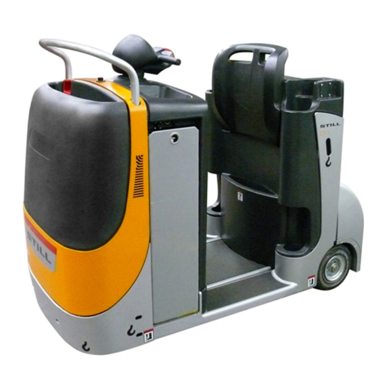
Overviews Overview Overview 1050_003-017 Battery connector Traction battery Cockpit Steering controller Button for driving in pedestrian mode Steering motor (option) Traction wheel Backrest Gearbox Pin coupling Traction motor Wheels Brake Traction controller Fuse carrier Platform Horn 51048070007 [EN]... -
Page 49: Operating Devices And Display Elements
Overviews Operating devices and display elements Operating devices and display elements View of controls 1050_003-005 Tray Button for driving in pedestrian mode Battery compartment lock (option) Cockpit Backrest Battery connector Button for driving in pedestrian mode Presence area (option) Tray Tray 51048070007 [EN]... -
Page 50: Tiller
Overviews Operating devices and display elements Tiller 6 7 8 1047_003-003 No function Numbers button No function button Hare Horn button Horn button button No function Tortoise (scrolling) button No function PRG ↑ Numbers button Handle Display Travel control (ON) button Emergency brake switch button Travel control... -
Page 51: Marking Positions
Overviews Marking positions Marking positions Location of plates and labels Warning label Warning label Battery plate "No attachment" symbol No attachment symbol Warning label Emergency halt symbol Hook symbol Vehicle identification plate Manufacturer’s logotype Manufacturer’s logotype and model label Customer’s logo (option) Hook symbol Serial number label (barcode on the chassis) 51048070007 [EN]... -
Page 52: Labels
Overviews Marking positions Labels Operating instructions Do not lift a load with the initial lift in the upper Slinging - See the operating instructions position UVV support (Germany only) Do not step under a raised load UVV plate (Germany only) Do not climb Company plate Do not stand on the forks... - Page 53 Overviews Marking positions On-board charger label Automatic mode selection indicator (EXU-H Mains connector (on-board charger) autolift only) "Plugs" label Manual or automatic mode selection Hydraulic filler (EXU-H autolift only) Maximum pressure (example) Automatic lifting/lowering mode selection Platform pressure diagram (example) Arrows Operating mode indication label Cold store...
-
Page 54: Chassis Frame Labelling
Overviews Marking positions Chassis frame labelling The truck’s serial number is marked on the chassis frame (1). OM2271 Data plate NOTE Please indicate the serial no. for all technical enquiries. Model Manufacturer Serial no. Year of manufacture Unladen weight (without battery) in kg Maximum battery weight Minimum battery weight Additional weight (ballast) in kg... -
Page 55: Options And Variants
Overviews Options and variants Options and variants Overview of options and models Designation Type Status Note PPS load wheels 250 X 85 mm Standard Polyurethane load wheels 75 shore, Version 250 X 80 mm Load wheels PPS load wheels, non-marking, 250 Variant X 85 mm Special versions upon request... - Page 56 Overviews Options and variants Designation Type Status Note Bow-shaped holder for accessories Option on powerhead Bow-shaped holder Bow-shaped holder for accessories Option on power unit on powerhead Bow-shaped holder for accessories Option at top on fork end Hour meter Standard Hour meter Hour meter, continuous Variant...
- Page 57 Overviews Options and variants Designation Type Status Note for 450 Ah battery, 800 Battery tray for 24 V/450 Ah battery, Battery frame Standard X 218 X 798, vertical and lateral removal Tray 97 Battery Battery Option Central water filling Central water filling unit Option unit Electrolyte circulation Electrolyte circulation...
-
Page 58: Battery Electrolyte Level Indicator Led (Optional)
Overviews Options and variants Battery electrolyte level indicator LED (optional) There are two versions of the LED: • 1) Located on the battery • 2) Located next to the battery plug. The LED indicates whether it is necessary to top up the distilled water in the battery. Operation: •... -
Page 59: Operation
Operation... -
Page 60: Pre-Shift-Checks
Operation Pre-shift-checks Pre-shift-checks Visual inspections WARNING Damages or any other defects on the truck or the attachment (option) can lead to accidents. If damages or any other defects on the truck or on attachment (option) are detected during the following checks, do not use the truck until it is properly repaired. -
Page 61: Check The Operation And Security Of The Trailer Coupling
Operation Pre-shift-checks Check the operation and security of the trailer coupling – Make sure that the tow pin (1) slides prop- erly into the trailer coupling (2) and engages securely when locked. – Make sure that the trailer coupling (2) is securely attached to the frame. -
Page 62: Commissioning
Operation Commissioning Commissioning Turning on the truck NOTE The pallet truck is equipped with a digital control and is taken into operation by entering a driver code. The driver code consists of four figures and is assigned by the pool manager. It is used for normal use and operation of the truck by the driver and operator. -
Page 63: Entering The User Code
Operation Commissioning After entering a digit, the display moves to the next position. The display shows a flashing line (9) (the illustration shows an example). NOTE If the digit entered is wrong, it is possible to cancel it by depressing the key (scroll) PRG ↑... -
Page 64: Starting With Fleetmanager (Optional)
Operation Commissioning Starting with FleetManager (op- tional) – Push the key (START) (6). Do not pay attention to the alert that appears in Code the display – Start the truck directly via the FleetManager keyboard or reading device, depending on the version. -
Page 65: Battery Charge
Operation Commissioning NOTE The factory setting of the battery charge indicator is for a lead battery. The indicator can also be set to a gel battery. Please contact your Service. • If a residual charge of 20% is reached, the battery must be charged soon. -
Page 66: Operating The Horn
Operation Commissioning Operating the horn – Press the horn button (2) on the tiller. 1047_003-008 Check of brake and presence area – Start the truck slowly with the throttle (1). – Step off the presence area (2) while leaving the throttle actuated. 1050_003-036 51048070007 [EN]... -
Page 67: Checking The Emergency Brake
Operation Commissioning Checking the emergency brake – Drive the truck slowly using the traction control (4). – Press the belly button (5). The truck is braked to a stop. – appears in the display (6). SToP NOTE After the disappearance of StoP in the display, press the (ON) button (7) to restart work. -
Page 68: Driving
Operation Driving Driving Driving safety rules Behaviour when driving The driver must drive within the plant accord- ing to the traffic rules for public roads. The speed of the truck must be consistent with the local conditions. Speed must be reduced, for example, in bends, narrow passages, when driving through swing doors, in areas where visibility is obstructed and on uneven ground. -
Page 69: Before Driving
Operation Driving immediately when eye contact wit the guide is lost. Before driving Persons in the danger area Before starting up, the driver must ensure that no person is standing in the danger area of the truck. If persons are at risk, a warning signal must be given in time. -
Page 70: Behaviour In Emergency Situations
Operation Driving Rules for roadways and working area Only the roadways released for traffic by the operator or his representative may be driven on. The roadways must be free of obstacles. The load may only be stacked and stored at the appropriate places. -
Page 71: Driving, Stand-On Mode
floor of the driver’s platform. WARNING Wait until the truck has come to a complete stand- still. Only then dismount on the side not used as 1044_501-001 roadway. 1050_003-002 51048070007 [EN]... -
Page 72: Selecting The Driving Mode
Operation Driving Forward travel – Depress the top part of the throttle (2) or (3) with the thumb. – The travel speed of the truck depends on how far the throttle is pushed. – When the throttle is released, the truck will be braked electrically. -
Page 73: Driving, Pedestrian Mode With Cockpit, Slow Speed With Throttle
Operation Driving Driving, pedestrian mode with cockpit, slow speed with throttle – Hold the cockpit at the handle (1) or (4) while standing beside the truck. NOTE The truck must be turned on. NOTE The throttle (2) or (3) on the cockpit can be operated with the right and left hand. - Page 74 Operation Driving – The travel speed of the truck depends on how far the throttle is pushed. – When the throttle is released, the truck will be braked electrically. Changing the direction of travel – Release the chosen direction of travel. –...
-
Page 75: Driving, Pedestrian Mode With Traction Button
Operation Driving CAUTION Take care when operating, especially if the user is not familiar with using this function. DANGER Risk of crushing feet. Do not use this function for turning. This function is designed to maintain à straight line. Proceed from the cockpit with very slight move- ments. -
Page 76: Steering
Operation Driving Steering The truck is steered by moving the tiller in range (1). 1390 mm 1047_003-018 Braking WARNING The stopping distance of the truck is affected by the condition of the floor surface. Take this into consideration when driving. Light braking –... - Page 77 Operation Driving – Leave the presence area (3). 1044_501-010 – Release the traction button (4) or (5). Moderate braking – Press the throttle (1) or (2) in the opposite direction. 1044_501-007 51048070007 [EN]...
-
Page 78: Emergency Stop Brake
Operation Driving Emergency stop brake CAUTION This brake may only be used in an emergency. – Depress the emergency brake switch (6). The truck is braked to a fast stop. – appears in the display (7). SToP NOTE After the disappearance of StoP in the display, press the (ON) button (8) to restart work. -
Page 79: Handling Trailers
Operation Handling trailers Handling trailers Approved towing applications NOTE The truck can be used to tow trailers. For this purpose it is provided with a trailer coupling. Maximum towed weight The rated drawbar pull for towing corresponds to the nominal drawbar pull stated on the vehicle identification plate of the tractor. - Page 80 Operation Handling trailers Example of use Force à la jante (N) The following load capacity diagram contains the following information: 1 Distance (km) 2 Driving speed (km/h) 3 Gradeability (%) (km/h) (km) 3000 4000 1000 2000 5000 4 Tractive force at the wheel (N) 5 Trailing load (kg) How to read the diagram: 4000 kg...
-
Page 81: Coupling Trailers
Operation Handling trailers Coupling trailers CAUTION When coupling and uncoupling trailers, the tractor and trailer must always be on level ground. Make sure that all controls are in the neutral position and the parking brake is applied. Before coupling a trailer, check if the draw bar of the trailer and the tow coupling of the tractor match. -
Page 82: Single-Position Or Multi-Position Trailer Coupling
Operation Handling trailers Single-position or multi-position trailer coupling Trailer coupling – Pull the tow pin (2) out. – Reverse the tractor slowly. DANGER Do not allow anyone to stand between the tractor and trailer during the approach. Always drive the trailer to the tractor. - Page 83 Operation Handling trailers Uncoupling – Step off the presence area (1). The tractor will be braked. – Secure the trailer with chocks or engage the trailer brake. 1047_003-039 – Turn the tow pin (2) 90° and pull it out of the trailer coupling (3).
-
Page 84: Automatically Closing Trailer Coupling
Operation Handling trailers Automatically closing trailer coupling Hitching up – Pull the safety lever (3). – Swivel the lever (2) up. – Release the brake on the front axle of the articulated drawbar trailer. CAUTION If this is not done, the coupling jaw, drawbar eye and support can be damaged! The drawbar eye must hit the centre of the coupling jaw when hitching up a rigid drawbar trailer. - Page 85 Operation Handling trailers Uncoupling – Step off the presence area (1). The tractors will be braked. – Secure the trailer with chocks or engage the trailer brake. – Pull the safety lever (3). – Swivel the lever (2) up. – Drive the tractor slowly forward. 1047_003-039 51048070007 [EN]...
-
Page 86: Rockinger Trailer Coupling
Operation Handling trailers ROCKINGER trailer coupling Hitching up – Swivel the lever (2) up. – Release the brake on the front axle of the articulated drawbar trailer. CAUTION If this is not done, the coupling jaw, drawbar eye and support can be damaged! The drawbar eye must hit the centre of the coupling jaw when hitching up a rigid drawbar trailer. -
Page 87: Towing A Trailer
Operation Handling trailers Towing a trailer NOTE Ensure that you understand how to operate any braking systems that may be fitted to trailers being towed. Ensure trailer load is secure, stable, evenly distributed on the trailer, and within the rated drawbar pull of the tractor. -
Page 88: Digicode
Operation Digicode Digicode Digicode control Access to the electronic control is granted with three different codes: • Driver’s code • master code • service code Driver’s code The driver’s code consists of four digits and must be created by the Pool Manager. It is used for the regular utilisation and opera- tion of the truck by the driver and operator. -
Page 89: Adding The Master Code
Operation Digicode Service code The service code is only intended for the after-sales service. It allows the diagnosis of the truck for inspections and the access to the driver’s and master code. Adding the master code NOTE The truck is turned off, the battery is connec- ted. -
Page 90: Deleting A Master Code
Operation Digicode – Confirm with the (enter) button (4). PRG ↲ 1044_505-012 A flashing line cursor (8) will appear in the display. – Enter the desired new 4-digit master code with the buttons (1), (2) or (3) as described above. NOTE The controller can store a maximum of five master codes. - Page 91 Operation Digicode – Press the (ON) button (5). – Enter the valid 4-digit master code with the buttons (1), (2) and (3). 1044_505-009 – Scroll with the (scrolling) button (6) PRG ↑ 1044_505-010 until (7) appears in the display. – Confirm with the (enter) button (4) PRG ↲...
-
Page 92: Adding A Driver's Code
Operation Digicode – Confirm with the (enter) button (4) PRG ↲ 1044_505-013 until the master code (9) to be deleted blinks (an example is shown). – Then release the button. (10) will 1044_505-015 appear again in the display. – Press the (scrolling) button (6) until PRG ↑... - Page 93 Operation Digicode – Scroll with the (scrolling) button (6) PRG ↑ 1044_505-016 until (7) appears in the display. USEr – Confirm with the (enter) button (4) PRG ↲ 1044_505-011 until (10) appears in the display. – Confirm with the (enter) button (4). PRG ↲...
-
Page 94: Deleting A Driver's Code
Operation Digicode Deleting a driver’s code NOTE The truck is turned off, the battery is connec- ted. – Press the (ON) button (5). – Enter the valid 4-digit master code with the buttons (1), (2) and (3). 1044_505-009 – Scroll with the (scrolling) button (6) PRG ↑... -
Page 95: Error Codes
Operation Error codes – Confirm with the (enter) button (4) PRG ↲ 1044_505-013 until the driver’s code (9) to be deleted blinks (an example is shown). – Then release the button. (10) will 1044_505-015 appear again in the display. – Press the (scrolling) button (6) until PRG ↑... -
Page 96: Error Code
Operation Error codes 1044_505-019 Error code Description Action Travel control operated at power-up. Release the travel control (1). E350 Left button operated at power-up. Release the left button (2). E370 Lift Lift Left button operated at power-up. Release the left button (3). -
Page 97: Handling The Truck In Specific Operating Conditions
Operation Handling the truck in specific operating conditions Handling the truck in specific operating conditions Transport – Disconnect the battery connector. Chocking the truck – Secure the truck against rolling and sliding with chocks (1). Lashing down the truck – Attach the lashing ropes (2) to the mast. 1050_003-008 Towing procedure As the electric brake is applied, the truck can-... -
Page 98: Hoisting The Truck
Operation Handling the battery Hoisting the truck CAUTION Only use a lifting gear and crane with a sufficient load capacity. See the vehicle identification plate for the loading weight. – For hoisting with a crane, always attach the slings to the points identified with the hook symbol (3). -
Page 99: Battery Weight And Dimensions
Operation Handling the battery Safe parking When the battery is being worked on, the truck must be properly parked and it may only be started when the battery cover is closed and the battery plug connected. Battery weight and dimensions The weight and size of the battery influence the stability of the truck. - Page 100 Operation Handling the battery – Disconnect the female battery connector (1). 1044_001-006 – Insert the key (2) into the battery lock and turn it 180°. Depress the battery lock. The battery cover (3) is unlocked and can be opened to rear. 1044_606-002 51048070007 [EN]...
- Page 101 Operation Handling the battery – Open the battery latch (4) 90°. 1050_003-022 Closing WARNING Danger of crushing. When closing the battery door, there should be nothing between battery door and edge of the frame. – Reconnect the female battery connector (3).
-
Page 102: Battery Replacement
Operation Handling the battery – Turn the key (5) for the battery compartment lock 180° and remove it. 1044_606-015 Battery replacement There are 2 ways of replacing the battery: 1. Vertically with a lifting tackle (all trucks) 2. With a lateral battery removal trolley (option) To avoid short circuits, cover batteries with unprotected terminals or connectors with a... -
Page 103: Battery Replacement With Crane
Operation Handling the battery Battery replacement with crane – Disconnect the battery connector. – Open the battery cover. – Release the battery. – Attach the battery (6) to a suitable lifting tackle (5). – The lifting tackle should exercise a vertical pull so that the battery tray is not squeezed together. -
Page 104: Servicing The Battery
Operation Decommissioning Servicing the battery Observe the applicable national regulations started when the battery cover is closed and for the installation and operation of battery the battery plug connected. charging units. Obey the operating instruc- tions for the charging unit or charger and the Battery servicing battery. -
Page 105: Storage
Operation Storage Storage Measures when taking the truck out of service for a long period If the truck is stored for a long period, carry out – Spray all open electric contacts with a the following corrosion protection measures. suitable contact spray. When taking the truck out of service for CAUTION over two months, park it in a clean and dry... - Page 106 Operation Storage 51048070007 [EN]...
-
Page 107: Maintenance
Maintenance... -
Page 108: General Maintenance Information
Maintenance General maintenance information General maintenance information General These instructions contain all the information required to perform the routine maintenance on your truck. Carry out the maintenance at the correct interval according to the main- tenance chart to keep your truck ready for operation, maintain its efficiency and prolong its service life and to benefit from the warranty. -
Page 109: Staff Training And Qualifications For Maintenance And Repairs
Maintenance General maintenance information Staff training and qualifications for maintenance and repairs Only qualified and authorized staff may carry out the maintenance. The annual inspec- tion must be performed by an expert. The expert must provide his opinion and safety assessment irrespective of operating and financial circumstances. -
Page 110: Maintenance And Inspection Intervals
Maintenance General maintenance information Maintenance and inspection intervals 1050_003-024 The services must be performed according to the following maintenance intervals. Item Service Clean the truck 3, 7 Service the wheels and rollers As needed Service the battery Service the braking system Service the gearbox 5, 6 Service the electric motors... -
Page 111: Ordering Spare Parts And Wear Parts
Maintenance General maintenance information Ordering spare parts and wear parts Spare parts are supplied by our after-sales service. Refer to the parts list for the required ordering information. Only use spare parts specified by the manu- facturer. Due to insufficient quality or incorrect assignment, the use of unapproved parts can increase the risk of accidents. -
Page 112: Maintenance Data Table
Maintenance Safety regulations for maintenance Maintenance data table Aids/ fluids and Assembly Type Specification Dimension/quantity lubricants Battery Distilled water needed - Insulation 1000 resistance Ohm min. against body Controls/joints Grease, with NLGI Multi S2 lithium base, needed MIL-L-2105, API: TOTAL gear oil Motor brushes - Steering motor Min. -
Page 113: Safety Devices
Maintenance Preparatory tasks for maintenance suitable precautions. Rings, metal bracelets, etc. must be removed before working on electric components. To prevent damage to electrical equipment with electronic components such as an electronic travel control or lift control, remove them from the vehicle before doing any electric welding. - Page 114 Maintenance Preparatory tasks for maintenance Jacking up at the frame – Jack up the truck until the wheels are clear of the ground. – Secure the truck. 1050_003-012 Removal The bonnet must be removed before servicing. Proceed as follows: – Remove the two screws (1) and (2). –...
-
Page 115: Cleaning
Maintenance Cleaning Installation – Install the cover Each of these materials to be handled (3) with the tabs (2) in the slots (1) into the frame from above. – Fasten the cover from above with two screws. 1050_003-025 Cleaning Clean the truck Washing instructions –... - Page 116 Maintenance Cleaning Cleaning the electrical system WARNING Do not point the steam-jet cleaner directly at electric motors and other electric components, brakes and bearings. NOTE Use only dry cleaning agents as cleaning agents. Do not remove covers, etc. – Clean electrical components with a non- metallic brush and blow dry with a weak jet of air.
-
Page 117: Maintenance As Required
Maintenance Maintenance as required Maintenance as required Service the wheels and rollers Check the tyres for wear and damage • The running surface of the traction wheel (2) and the rear wheels (1) should be undamaged. Dimensions Traction wheel 250 x 100 mm Rear wheels 250 x 80 mm –... - Page 118 Maintenance Maintenance as required Battery maintenance precautions Keep the battery cell lid dry and clean. Neu- tralise spilled electrolyte immediately. Termi- nals and cable lugs should be clean, slightly greased with terminal grease and screwed on securely. Battery charging During charging, keep the surface of the battery cells exposed in order to provide sufficient ventilation.
-
Page 119: Charging The Lead Battery
Maintenance Maintenance as required Charging the lead battery WARNING The battery could be damaged, shorted or an explosion could occur. Do not place any metallic objects or tools on the battery. No naked lights, no smoking permitted! WARNING The electrolyte (diluted sulphuric acid) is poisonous and caustic! 1044_606-008 Follow the safety precautions for handling battery... -
Page 120: Fuses
Maintenance Maintenance as required – Connect the battery plug (2) to the connec- tor of the charger unit. NOTE Please follow the information in the operating instructions for the battery and the charging station (equalising charge). WARNING The gases released during charging are explosive. –... - Page 121 Maintenance Maintenance as required Steering fuse 20 A Fuse for other power circuits 1044_604-002 1050_003-028 51048070007 [EN]...
- Page 122 Maintenance Maintenance as required 51048070007 [EN]...
-
Page 123: Maintenance Every 500 Hours
Maintenance Maintenance every 500 hours Maintenance every 500 hours Other tasks – Perform all maintenance work; see the "Maintenance" chapter. Checking the gearbox oil level NOTE The truck must stand on level ground. – Turn the tiller until the level plug (1) is visible. –... -
Page 124: Service The Electric Motors
Maintenance Maintenance every 500 hours Service the electric motors Check the cable connections – Check the traction motor (2) and steering motor (1) leads for proper security, condi- tion and insulation. NOTE Corroded connections and broken cables lead to drops in voltage, leading to malfunctions. –... - Page 125 Maintenance Maintenance every 500 hours 1047_003-041 NOTE Brushes under the wear limit must be replaced as sets. Before installation, check the commu- tator for pitting. New brushes must ground in. When reinstalling existing brushes, do not in- stall them in the wrong direction or interchange them.
-
Page 126: Service The Electrical System
Maintenance Maintenance every 500 hours 1044_110-004 Service the electrical system Check connections and fuses DANGER – Before beginning the following services, park the truck and disconnect the battery connector. – Remove the front cover. – Check the fuses (1) for proper condition. –... -
Page 127: Service The Braking System
Maintenance Maintenance every 500 hours Service the braking system Check clearance – Release the brake. – Measure the air gap (1) with an adjustment shim at three different points separated by 120°. Min. clearance: 0.3 mm Max. clearance: 0.8 mm WARNING –... - Page 128 Maintenance Maintenance every 500 hours 51048070007 [EN]...
-
Page 129: Annual Maintenance
Maintenance Annual maintenance Annual maintenance Work that must also be carried out – Carry out maintenance work as neces- sary, see ⇒ Chapter "Maintenance as re- quired", P. 109. – Carry out 500-hour maintenance, see ⇒ Chapter "Maintenance every 500 hours", P. - Page 130 Maintenance Annual maintenance 51048070007 [EN]...
-
Page 131: Maintenance Every 2000 Hours
Maintenance Maintenance every 2000 hours Maintenance every 2000 hours Other tasks – Carry out the services of the maintenance as required, see ⇒ Chapter "Maintenance as required", P. 109. – Carry out the 500-hour maintenance, see ⇒ Chapter "Maintenance every 500 hours", P. - Page 132 Maintenance Maintenance every 2000 hours Testing the insulation resistance of the electrical system Have the insulation resistance of all active electrical components checked in accordance with DIN 57117 and DIN 43539, VDE 0117 and VDE 0520. Measurement voltage > nominal voltage < 500 V.
-
Page 133: Maintenance Every 5000 Hours
Maintenance Maintenance every 5000 hours Maintenance every 5000 hours Other tasks – Carry out the services of the maintenance as required, see ⇒ Chapter "Maintenance as required", P. 109. – Carry out the 500-hour maintenance, see ⇒ Chapter "Maintenance every 500 hours", P. - Page 134 Maintenance Maintenance every 5000 hours 51048070007 [EN]...
-
Page 135: Technical Data
Technical data... -
Page 136: Dimensions
Technical data Dimensions Dimensions 1050_003-032 51048070007 [EN]... -
Page 137: Technical Data (Vdi) Cx-T
Technical data Technical data (VDI) CX-T Technical data (VDI) CX-T Characteristics CX-T Manufacturer STILL GmbH Power source: Electric, diesel, Battery petrol, LP gas, mains power Operation: Hand, pedestrian, Stand-on stand-on, seated, order picker 4000 Nominal capacity/load Q (kg) Drawbar pull... - Page 138 Technical data Technical data (VDI) CX-T CX-T Distance of trailer coupling from l5 (mm) rear axle Overall length, without load l1 (mm) 1573 b1 (mm) Overall length of frame Ground clearance, centre of m2 (mm) wheelbase Turning radius Wa (mm) 1390 Performances CX-T...
-
Page 139: Wheels And Tyres
Technical data Wheels and tyres Miscellaneous CX-T Frequency Type of drive control converter Noise level, at operator’s ear dB (A) Trailer coupling, designa- tion/type acc. to DIN Wheels and tyres Approved types of tyres Only the specified types of wheels may be installed. - Page 140 Technical data Wheels and tyres 51048070007 [EN]...
- Page 141 Index Checking the gearbox oil level ..115 Chocking the truck ....89 Adding a driver’s code ....84 Clean the truck .
- Page 142 Index Maintenance personnel for batteries . . . 101 Maintenance staff ....90 EC declaration of conformity in Master code ..... . 80 accordance with Machinery Directive .
- Page 143 Index Reversing ....64 – 65 Steering ......68 Reversing with traction button .
- Page 146 STILL GmbH Berzeliusstrasse 10 D-22113 Hamburg Ident no. 51048070007 EN...
Need help?
Do you have a question about the CX-T-40 and is the answer not in the manual?
Questions and answers